- 您現(xiàn)在的位置:買賣IC網(wǎng) > PDF目錄361030 > LM56CIMMX (National Semiconductor Corporation) Dual Output Low Power Thermostat PDF資料下載
參數(shù)資料
| 型號(hào): | LM56CIMMX |
| 廠商: | National Semiconductor Corporation |
| 元件分類: | 溫度傳感器 |
| 英文描述: | Dual Output Low Power Thermostat |
| 中文描述: | 雙路輸出低功耗溫控器 |
| 文件頁(yè)數(shù): | 10/13頁(yè) |
| 文件大小: | 370K |
| 代理商: | LM56CIMMX |
第1頁(yè)第2頁(yè)第3頁(yè)第4頁(yè)第5頁(yè)第6頁(yè)第7頁(yè)第8頁(yè)第9頁(yè)當(dāng)前第10頁(yè)第11頁(yè)第12頁(yè)第13頁(yè)
Application Hints
(Continued)
5.0
V
REF
AND V
TEMP
CAPACTIVE LOADING
The LM56 V
REF
and V
TEMP
outputs handle capacitive load-
ing well. Without any special precautions, these outputs can
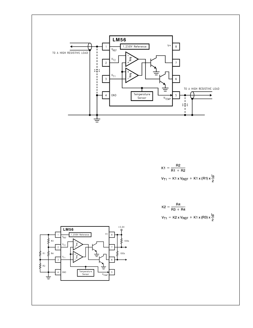
drive any capacitive load as shown in Figure 4 .
6.0
Over the specified temperature range the LM56 V
out-
put has a maximum output impedance of 1500
. In an ex-
tremely noisy environment it may be necessary to add some
filtering to minimize noise pickup. It is recommended that 0.1
μF be added from V
+
to GND to bypass the power supply
voltage, as shown in Figure 4. In a noisy environment it may
be necessary to add a capacitor from the V
output to
ground. A 1 μF output capacitor with the 1500
output im-
pedance will form a 106 Hz lowpass filter. Since the thermal
time constant of the V
output is much slower than the
9.4 ms time constant formed by the RC, the overall response
time of the V
output will not be significantly affected. For
much larger capacitors this additional time lag will increase
the overall response time of the LM56.
NOISY ENVIRONMENTS
7.0
APPLICATIONS CIRCUITS
The circuit shown inFigure 5 will reduce the effective bias
current error for V
T2
as discussed in Section 3.0 to be
equivalent to the error term of V
T1
. For this circuit the effect
of the bias current on the first trip point can be defined by the
following equations:
where I
B
= 300 nA (the maximum specified error).
Similarly, bias current affect on V
T2
can be defined by:
where I
B
= 300 nA (the maximum specified error).
The current shown in Figure 6 is a simple overtemperature
detector for power devices. In this example, an audio power
amplifier IC is bolted to a heat sink and an LM56 Celsius
temperature sensor is mounted on a PC board that is bolted
to the heat sink near the power amplifier. To ensure that the
sensing element is at the same temperature as the heat sink,
the sensor’s leads are mounted to pads that have feed
throughs to the back side of the PC board. Since the LM56 is
sensing the temperature of the actual PC board the back
side of the PC board also has large ground plane to help
conduct the heat to the device. The comparator’s output
goes low if the heat sink temperature rises above a threshold
set by R1, R2, and the voltage reference. This fault detection
output from the comparator now can be used to turn on a
cooling fan. The circuit as shown in design to turn the fan on
when heat sink temperature exceeds about 80C, and to turn
the fan off when the heat sink temperature falls below ap-
proximately 75C.
DS012893-19
FIGURE 4. Loading of V
REF
and V
TEMP
DS012893-20
FIGURE 5. Reducing Errors Caused by Bias Current
L
www.national.com
10
相關(guān)PDF資料 |
PDF描述 |
|---|---|
| LM56CIMX | Dual Output Low Power Thermostat |
| LM6041IN | CONNECTOR |
| LMC6041 | CMOS Single Micropower Operational Amplifier |
| LMC6041AIM | CMOS Single Micropower Operational Amplifier |
| LMC6041AIN | CMOS Single Micropower Operational Amplifier |
相關(guān)代理商/技術(shù)參數(shù) |
參數(shù)描述 |
|---|---|
| LM56CIMMX/NOPB | 功能描述:恒溫器 RoHS:否 制造商:Maxim Integrated 功能: 開路溫度: 閉合溫度: 準(zhǔn)確性:+/- 1 C 溫度范圍:- 55 C to + 125 C 電流額定值:500 uA 電壓額定值:2.7 V to 5.5 V 產(chǎn)品:Thermostats |
| LM56CIMX | 功能描述:恒溫器 RoHS:否 制造商:Maxim Integrated 功能: 開路溫度: 閉合溫度: 準(zhǔn)確性:+/- 1 C 溫度范圍:- 55 C to + 125 C 電流額定值:500 uA 電壓額定值:2.7 V to 5.5 V 產(chǎn)品:Thermostats |
| LM56CIMX/NOPB | 功能描述:恒溫器 RoHS:否 制造商:Maxim Integrated 功能: 開路溫度: 閉合溫度: 準(zhǔn)確性:+/- 1 C 溫度范圍:- 55 C to + 125 C 電流額定值:500 uA 電壓額定值:2.7 V to 5.5 V 產(chǎn)品:Thermostats |
| LM57 | 制造商:NSC 制造商全稱:National Semiconductor 功能描述:Resistor-Programmable Temperature Switch and Analog Temperature Sensor |
| LM570Z | 制造商:SEOUL 制造商全稱:Seoul Semiconductor 功能描述:GREEN OVAL LAMP LED |
發(fā)布緊急采購(gòu),3分鐘左右您將得到回復(fù)。