- 您現(xiàn)在的位置:買賣IC網(wǎng) > PDF目錄361030 > LM556CN (FAIRCHILD SEMICONDUCTOR CORP) Dual Timer PDF資料下載
參數(shù)資料
| 型號: | LM556CN |
| 廠商: | FAIRCHILD SEMICONDUCTOR CORP |
| 元件分類: | 運(yùn)動控制電子 |
| 英文描述: | Dual Timer |
| 中文描述: | DUAL PULSE; RECTANGULAR, TIMER, PDIP14 |
| 封裝: | DIP-14 |
| 文件頁數(shù): | 3/8頁 |
| 文件大?。?/td> | 216K |
| 代理商: | LM556CN |
Absolute Maximum Ratings
(Note 1)
If Military/Aerospace specified devices are required,
please contact the National Semiconductor Sales Office/
Distributors for availability and specifications.
Supply Voltage
Power Dissipation (Note 2)
LM556CM
LM556CN
Operating Temperature Ranges
LM556C
+18V
410 mW
1620 mW
0C to +70C
Storage Temperature Range
Soldering Information
Dual-In-Line Package
Soldering (10 Seconds)
Small Outline Packages
Vapor Phase (60 Seconds)
Infrared (15 Seconds)
See AN-450 “Surface Mounting Methods and Their Effect
on Product Reliability” for other methods of soldering
surface mount devices.
65C to +150C
260C
215C
220C
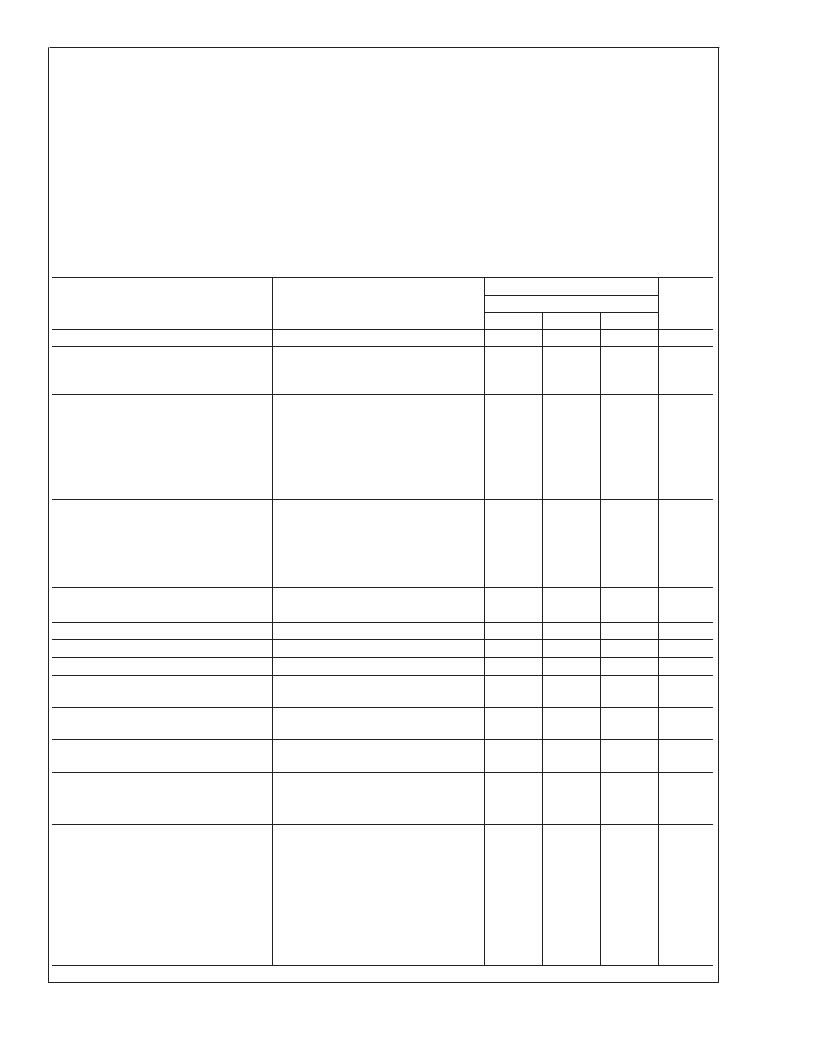
Electrical Characteristics
(T
A
= 25C, V
CC
= +5V to +15V, unless otherwise specified)
Parameter
Conditions
Limits
LM556C
Typ
Units
Min
4.5
Max
16
6
14
Supply Voltage
Supply Current
(Each Timer Section)
V
V
CC
= 5V, R
L
=
∞
V
CC
= 15V, R
L
=
∞
(Low State) (Note 3)
3
10
mA
Timing Error, Monostable
Initial Accuracy
Drift with Temperature
0.75
50
%
R
A
= 1k to 100k
,
C = 0.1μF, (Note 4)
ppm/C
Accuracy over Temperature
Drift with Supply
Timing Error, Astable
Initial Accuracy
Drift with Temperature
Accuracy over Temperature
Drift with Supply
Trigger Voltage
1.5
0.1
%
%/V
2.25
150
3.0
0.30
5
1.67
0.2
0.5
0.1
0.03
%
R
A
, R
B
= 1k to 100k
,
C = 0.1μF, (Note 4)
ppm/C
%
%/V
V
V
μA
V
mA
μA
nA
V
CC
= 15V
V
CC
= 5V
4.5
1.25
5.5
2.0
1.0
1
0.6
0.1
250
11
4
100
Trigger Current
Reset Voltage
Reset Current
Threshold Current
0.4
V
TH
= V-Control (Note 6)
V
TH
= 11.2V
V
CC
= 15V
V
CC
= 5V
Control Voltage Level and
Threshold Voltage
Pin 1, 13
Leakage Output High
Pin 1, 13 Sat
Output Low
Output Low
Output Voltage Drop (Low)
9
2.6
10
3.33
1
V
nA
(Note 7)
V
CC
= 15V, I = 15mA
V
CC
= 4.5V, I = 4.5mA
V
CC
= 15V
I
SINK
= 10mA
I
SINK
= 50mA
I
SINK
= 100mA
I
SINK
= 200mA
V
CC
= 5V
I
SINK
= 8mA
I
SINK
= 5mA
180
80
300
200
mV
mV
0.1
0.4
2
2.5
0.25
0.75
2.75
V
V
V
V
V
V
0.25
0.35
L
www.national.com
3
相關(guān)PDF資料 |
PDF描述 |
|---|---|
| LM5642 | High Voltage, Dual Synchronous Buck Converter with Oscillator Synchronization |
| LM5642MTC | High Voltage, Dual Synchronous Buck Converter with Oscillator Synchronization |
| LM565 | Phase Locked Loop |
| LM565C | |
| LM565CH | Analog Phase-Locked Loop |
相關(guān)代理商/技術(shù)參數(shù) |
參數(shù)描述 |
|---|---|
| LM556CN NOPB | 制造商:National Semiconductor 功能描述:Standard Timer Dual 14-Pin PDIP Rail |
| LM556CN | 制造商:Texas Instruments 功能描述:IC TIMER DUAL DIP14 556 |
| LM556CN | 制造商:Fairchild Semiconductor Corporation 功能描述:TIMER IC |
| LM556CN/A+ | 制造商:未知廠家 制造商全稱:未知廠家 功能描述:Analog Timer Circuit |
| LM556CN/B+ | 制造商:未知廠家 制造商全稱:未知廠家 功能描述:Analog Timer Circuit |
發(fā)布緊急采購,3分鐘左右您將得到回復(fù)。