- 您現(xiàn)在的位置:買賣IC網(wǎng) > PDF目錄30752 > LM4838MT/NOPB (NATIONAL SEMICONDUCTOR CORP) 2 CHANNEL(S), VOLUME CONTROL CIRCUIT, PDSO28 PDF資料下載
參數(shù)資料
| 型號(hào): | LM4838MT/NOPB |
| 廠商: | NATIONAL SEMICONDUCTOR CORP |
| 元件分類: | 音頻控制 |
| 英文描述: | 2 CHANNEL(S), VOLUME CONTROL CIRCUIT, PDSO28 |
| 封裝: | TSSOP-28 |
| 文件頁(yè)數(shù): | 13/38頁(yè) |
| 文件大?。?/td> | 2351K |
| 代理商: | LM4838MT/NOPB |
第1頁(yè)第2頁(yè)第3頁(yè)第4頁(yè)第5頁(yè)第6頁(yè)第7頁(yè)第8頁(yè)第9頁(yè)第10頁(yè)第11頁(yè)第12頁(yè)當(dāng)前第13頁(yè)第14頁(yè)第15頁(yè)第16頁(yè)第17頁(yè)第18頁(yè)第19頁(yè)第20頁(yè)第21頁(yè)第22頁(yè)第23頁(yè)第24頁(yè)第25頁(yè)第26頁(yè)第27頁(yè)第28頁(yè)第29頁(yè)第30頁(yè)第31頁(yè)第32頁(yè)第33頁(yè)第34頁(yè)第35頁(yè)第36頁(yè)第37頁(yè)第38頁(yè)

Application Information (Continued)
GAIN SELECT FUNCTION (Bass Boost)
The LM4838 features selectable gain, using either internal or
external feedback resistors. Either set of feedback resistors
set the gain of the output amplifiers. The voltage applied to
the GAIN SELECT pin controls which gain is selected. Ap-
plying V
DD to the GAIN SELECT pin selects the external gain
mode. Applying 0V to the GAIN SELECT pin selects the
internally set unity gain.
In some cases a designer may want to improve the low
frequency response of the bridged amplifier or incorporate a
bass boost feature. This bass boost can be useful in systems
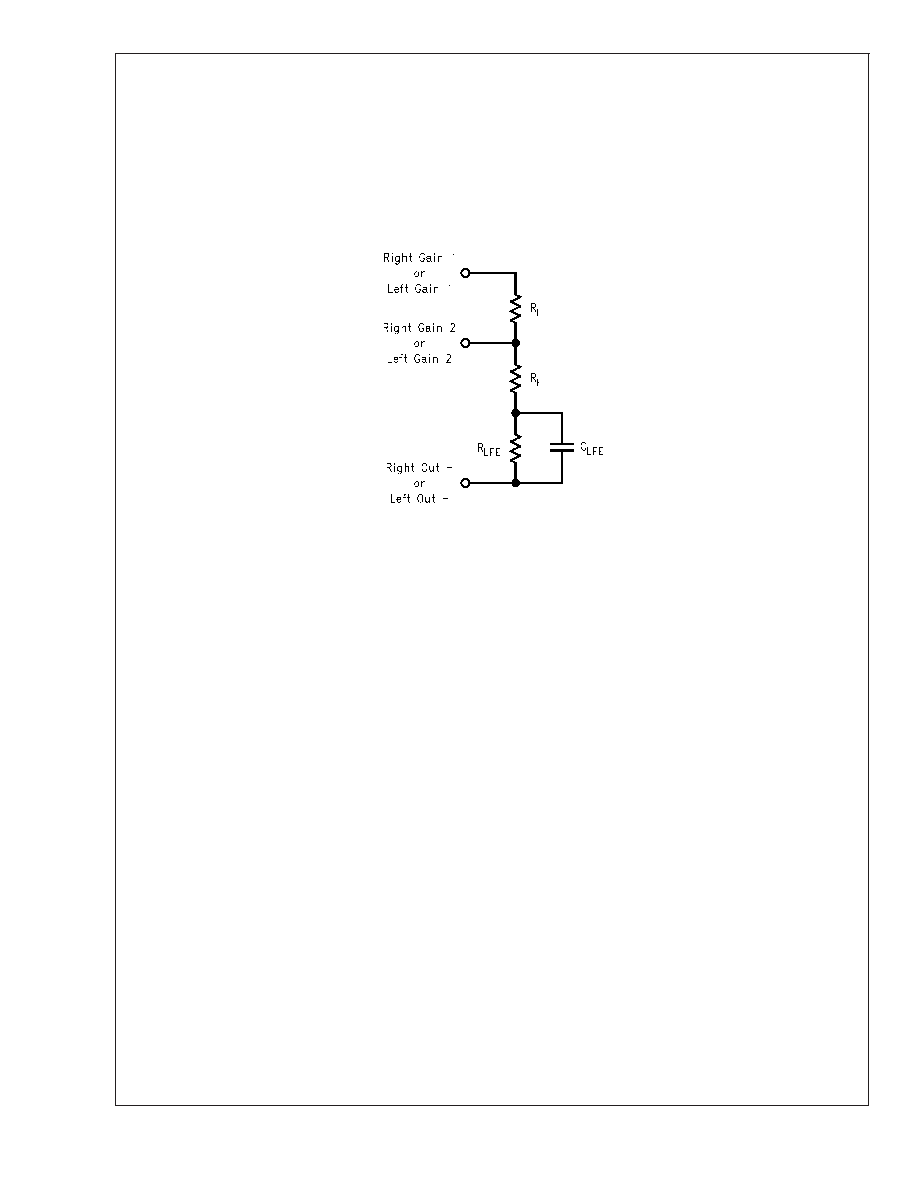
where speakers are housed in small enclosures. A resistor,
R
LFE, and a capacitor, CLFE, in parallel, can be placed in
series with the feedback resistor of the bridged amplifier as
seen in Figure 4.
At low, frequencies C
LFE is a virtual open circuit and at high
frequencies, its nearly zero ohm impedance shorts R
LFE.
The result is increased bridge-amplifier gain at low frequen-
cies. The combination of R
LFE and CLFE form a -6dB corner
frequency at
f
C = 1/(2
πR
LFEC LFE)
(9)
The bridged-amplifier low frequency differential gain is:
A
VD = 2(RF +RLFE)/R i
(10)
Using the component values shown in Figure 1 (R
F = 20k
,
R
LFE = 20k
, and C
LFE = 0.068F), a first-order, -6dB pole is
created at 120Hz. Assuming R
i = 20k
, the low frequency
differential gain is 4. The input (C
i) and output (CO) capacitor
values must be selected for a low frequency response that
covers the range of frequencies affected by the desired
bass-boost operation.
DC VOLUME CONTROL
The LM4838 has an internal stereo volume control whose
setting is a function of the DC voltage applied to the DC VOL
CONTROL pin.
The LM4838 volume control consists of 31 steps that are
individually selected by a variable DC voltage level on the
volume control pin. The range of the steps, controlled by the
DC voltage, are from 0dB - 78dB. Each gain step corre-
sponds to a specific input voltage range, as shown in table 2.
To minimize the effect of noise on the volume control pin,
which can affect the selected gain level, hysteresis has been
implemented. The amount of hysteresis corresponds to half
of the step width, as shown in Volume Control Characteriza-
tion Graph (DS200133-40).
For highest accuracy, the voltage shown in the ’recom-
mended voltage’ column of the table is used to select a
desired gain. This recommended voltage is exactly halfway
between the two nearest transitions to the next highest or
next lowest gain levels.
The gain levels are 1dB/step from 0dB to -6dB, 2dB/step
from -6dB to -36dB, 3dB/step from -36dB to -47dB, 4dB/step
from -47db to -51dB, 5dB/step from -51dB to -66dB, and
12dB to the last step at -78dB.
20013311
FIGURE 4. Low Frequency Enhancement
LM4838
www.national.com
20
相關(guān)PDF資料 |
PDF描述 |
|---|---|
| LM4838ITL/NOPB | 2 CHANNEL(S), VOLUME CONTROL CIRCUIT, PBGA36 |
| LM4838ITLX/NOPB | 2 CHANNEL(S), VOLUME CONTROL CIRCUIT, PBGA36 |
| LM4838LQ/NOPB | 2 CHANNEL(S), VOLUME CONTROL CIRCUIT, QCC28 |
| LM4838LQX/NOPB | 2 CHANNEL(S), VOLUME CONTROL CIRCUIT, QCC28 |
| LM4839MTE/NOPB | 2 CHANNEL(S), TONE CONTROL CIRCUIT, PDSO28 |
相關(guān)代理商/技術(shù)參數(shù) |
參數(shù)描述 |
|---|---|
| LM4838MTX | 功能描述:音頻放大器 RoHS:否 制造商:STMicroelectronics 產(chǎn)品:General Purpose Audio Amplifiers 輸出類型:Digital 輸出功率: THD + 噪聲: 工作電源電壓:3.3 V 電源電流: 最大功率耗散: 最大工作溫度: 安裝風(fēng)格:SMD/SMT 封裝 / 箱體:TQFP-64 封裝:Reel |
| LM4838MTX/NOPB | 功能描述:音頻放大器 RoHS:否 制造商:STMicroelectronics 產(chǎn)品:General Purpose Audio Amplifiers 輸出類型:Digital 輸出功率: THD + 噪聲: 工作電源電壓:3.3 V 電源電流: 最大功率耗散: 最大工作溫度: 安裝風(fēng)格:SMD/SMT 封裝 / 箱體:TQFP-64 封裝:Reel |
| LM4839 | 制造商:NSC 制造商全稱:National Semiconductor 功能描述:Stereo 2W Audio Power Amplifiers with DC Volume Control, Bass Boost, and Input Mux |
| LM4839A E WAF | 制造商:Texas Instruments 功能描述: |
| LM4839LQ | 制造商:Texas Instruments 功能描述:AMP AUDIO POWER DC VOLT LLP-28 |
發(fā)布緊急采購(gòu),3分鐘左右您將得到回復(fù)。
