- 您現(xiàn)在的位置:買(mǎi)賣(mài)IC網(wǎng) > PDF目錄361024 > LM2599T-ADJ (NATIONAL SEMICONDUCTOR CORP) SIMPLE SWITCHER Power Converter 150 kHz 3A Step-Down Voltage Regulator, with Features PDF資料下載
參數(shù)資料
| 型號(hào): | LM2599T-ADJ |
| 廠商: | NATIONAL SEMICONDUCTOR CORP |
| 元件分類(lèi): | 穩(wěn)壓器 |
| 英文描述: | SIMPLE SWITCHER Power Converter 150 kHz 3A Step-Down Voltage Regulator, with Features |
| 中文描述: | 7.5 A SWITCHING REGULATOR, 173 kHz SWITCHING FREQ-MAX, PZFM7 |
| 封裝: | TO-220, 7 PIN |
| 文件頁(yè)數(shù): | 24/31頁(yè) |
| 文件大小: | 812K |
| 代理商: | LM2599T-ADJ |
第1頁(yè)第2頁(yè)第3頁(yè)第4頁(yè)第5頁(yè)第6頁(yè)第7頁(yè)第8頁(yè)第9頁(yè)第10頁(yè)第11頁(yè)第12頁(yè)第13頁(yè)第14頁(yè)第15頁(yè)第16頁(yè)第17頁(yè)第18頁(yè)第19頁(yè)第20頁(yè)第21頁(yè)第22頁(yè)第23頁(yè)當(dāng)前第24頁(yè)第25頁(yè)第26頁(yè)第27頁(yè)第28頁(yè)第29頁(yè)第30頁(yè)第31頁(yè)
Application Information
(Continued)
These magnetic lines of flux will induce a voltage into any
wire or PC board copper trace that comes within the induc-
tor’s magnetic field. The strength of the magnetic field, the
orientation and location of the PC copper trace to the mag-
netic field, and the distance between the copper trace and
the inductor, determine the amount of voltage generated in
the copper trace. Another way of looking at this inductive
coupling is to consider the PC board copper trace as one
turn of a transformer (secondary) with the inductor winding
as the primary. Many millivolts can be generated in a copper
trace located near an open core inductor which can cause
stability problems or high output ripple voltage problems.
If unstable operation is seen, and an open core inductor is
used, it’s possible that the location of the inductor with re-
spect to other PC traces may be the problem. To determine
if this is the problem, temporarily raise the inductor away
from the board by several inches and then check circuit op-
eration. If the circuit now operates correctly, then the mag-
netic flux from the open core inductor is causing the problem.
Substituting a closed core inductor such as a torroid or
E-core will correct the problem, or re-arranging the PC layout
may be necessary. Magnetic flux cutting the IC device
ground trace, feedback trace, or the positive or negative
traces of the output capacitor should be minimized.
Sometimes, locating a trace directly beneath a bobbin in-
ductor will provide good results, provided it is exactly in the
center of the inductor (because the induced voltages cancel
themselves out), but if it is off center one direction or the
other, then problems could arise. If flux problems are
present, even the direction of the inductor winding can make
a difference in some circuits.
This discussion on open core inductors is not to frighten the
user, but to alert the user on what kind of problems to watch
out for when using them. Open core bobbin or “stick” induc-
tors are an inexpensive, simple way of making a compact ef-
ficient inductor, and they are used by the millions in many dif-
ferent applications.
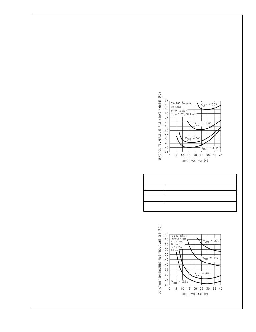
THERMAL CONSIDERATIONS
The LM2599 is available in two packages, a 7-pin TO-220
(T) and a 7-pin surface mount TO-263 (S).
The TO-220 package needs a heat sink under most condi-
tions. The size of the heat sink depends on the input voltage,
the output voltage, the load current and the ambient tem-
perature. The curves in Figure 21 show the LM2599T junc-
tion temperature rises above ambient temperature for a 3A
load and different input and output voltages. The data for
these curves was taken with the LM2599T (TO-220 pack-
age) operating as a buck switching regulator in an ambient
temperature of 25C (still air). These temperature rise num-
bers are all approximate and there are many factors that can
affect these temperatures. Higher ambient temperatures re-
quire more heat sinking.
The TO-263 surface mount package tab is designed to be
soldered to the copper on a printed circuit board. The copper
and the board are the heat sink for this package and the
other heat producing components, such as the catch diode
and inductor. The pc board copper area that the package is
soldered to should be at least 0.4 in
2
, and ideally should
have 2 or more square inches of 2 oz. (0.0028 in) copper.
Additional copper area improves the thermal characteristics,
but with copper areas greater than approximately 6 in
2
, only
small improvements in heat dissipation are realized. If fur-
ther thermal improvements are needed, double sided, multi-
layer pc-board with large copper areas and/or airflow are
recommended.
The curves shown in Figure 22 show the LM2599S (TO-263
package) junction temperature rise above ambient tempera-
ture with a 2Aload for various input and output voltages. This
data was taken with the circuit operating as a buck switching
regulator with all components mounted on a pc board to
simulate the junction temperature under actual operating
conditions. This curve can be used for a quick check for the
approximate junction temperature for various conditions, but
be aware that there are many factors that can affect the junc-
tion temperature. When load currents higher than 2A are
used, double sided or multilayer pc-boards with large copper
areas and/or airflow might be needed, especially for high
ambient temperatures and high output voltages.
DS012582-38
Circuit Data for Temperature Rise Curve TO-220
Package (T)
Capacitors
Through hole electrolytic
Inductor
Through hole Renco
Diode
Through hole, 5A 40V, Schottky
PC board
3 square inches single sided 2 oz. copper
(0.0028")
FIGURE 21. Junction Temperature Rise, TO-220
DS012582-39
L
www.national.com
24
相關(guān)PDF資料 |
PDF描述 |
|---|---|
| LM2619MTC | 500mA Step-Down DC-DC Converter |
| LM2619MTCX | 500mA Step-Down DC-DC Converter |
| LM2621MM | Low Input Voltage, Step-Up DC-DC Converter |
| LM2621 | |
| LM2622 | |
相關(guān)代理商/技術(shù)參數(shù) |
參數(shù)描述 |
|---|---|
| LM2599T-ADJ | 制造商:Texas Instruments 功能描述:SWITCHING REG 3A ADJ 2599 TO2207 |
| LM2599T-ADJ/NOPB | 功能描述:直流/直流開(kāi)關(guān)轉(zhuǎn)換器 RoHS:否 制造商:STMicroelectronics 最大輸入電壓:4.5 V 開(kāi)關(guān)頻率:1.5 MHz 輸出電壓:4.6 V 輸出電流:250 mA 輸出端數(shù)量:2 最大工作溫度:+ 85 C 安裝風(fēng)格:SMD/SMT |
| LM26 | 制造商:Psiber Data Systems 功能描述:LanMaster 26 Pro Link Tester and Accesory Kit |
| LM26_07 | 制造商:NSC 制造商全稱(chēng):National Semiconductor 功能描述:SOT-23, ±3°C Accurate, Factory Preset Thermostat |
| LM26001 | 制造商:NSC 制造商全稱(chēng):National Semiconductor 功能描述:1.5A Switching Regulator with High Efficiency Sleep Mode |
發(fā)布緊急采購(gòu),3分鐘左右您將得到回復(fù)。