- 您現(xiàn)在的位置:買賣IC網(wǎng) > PDF目錄361023 > LM1558J (NATIONAL SEMICONDUCTOR CORP) Dual Operational Amplifier PDF資料下載
參數(shù)資料
| 型號: | LM1558J |
| 廠商: | NATIONAL SEMICONDUCTOR CORP |
| 元件分類: | 運算放大器 |
| 英文描述: | Dual Operational Amplifier |
| 中文描述: | DUAL OP-AMP, 6000 uV OFFSET-MAX, 1 MHz BAND WIDTH, CDIP8 |
| 封裝: | CERDIP-8 |
| 文件頁數(shù): | 3/6頁 |
| 文件大?。?/td> | 124K |
| 代理商: | LM1558J |
Absolute Maximum Ratings
(Note 1)
If Military/Aerospace specified devices are required,
please contact the National Semiconductor Sales Office/
Distributors for availability and specifications.
(Note 5)
Supply Voltage
LM1558
LM1458
Power Dissipation (Note 2)
LM1558H/LM1458H
LM1458N
Differential Input Voltage
Input Voltage (Note 3)
Output Short-Circuit Duration
±
22V
±
18V
500 mW
400 mW
±
30V
±
15V
Continuous
Operating Temperature Range
LM1558
LM1458
Storage Temperature Range
Lead Temperature (Soldering, 10 sec.)
Soldering Information
Dual-In-Line Package
Soldering (10 seconds)
Small Outline Package
Vapor Phase (60 seconds)
Infrared (15 seconds)
See AN-450 “Surface Mounting Methods and Their Effect
on Product Reliability” for other methods of soldering
surface mount devices.
ESD tolerance (Note 6)
55C to +125C
0C to +70C
65C to +150C
260C
260C
215C
220C
300V
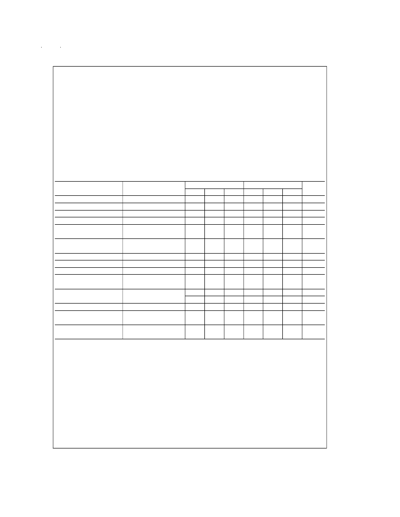
Electrical Characteristics
(Note 4)
Parameter
Conditions
LM1558
Typ
1.0
80
200
1.0
3.0
LM1458
Typ
1.0
80
200
1.0
3.0
Units
Min
Max
5.0
200
500
Min
Max
6.0
200
500
Input Offset Voltage
Input Offset Current
Input Bias Current
Input Resistance
Supply Current Both
Amplifiers
Large Signal Voltage Gain
T
A
= 25C, R
S
≤
10 k
T
A
= 25C
T
A
= 25C
T
A
= 25C
T
A
= 25C, V
S
=
±
15V
mV
nA
nA
M
mA
0.3
0.3
5.0
5.6
T
A
= 25C, V
S
=
±
15V
V
OUT
=
±
10V, R
L
≥
2 k
R
S
≤
10 k
50
160
20
160
V/mV
Input Offset Voltage
Input Offset Current
Input Bias Current
Large Signal Voltage Gain
6.0
500
1.5
7.5
300
0.8
mV
nA
μA
V/mV
V
S
=
±
15V, V
OUT
=
±
10V
R
L
≥
k
V
S
=
±
15V, R
L
= 10 k
R
L
= 2 k
V
S
=
±
15V
R
S
≤
10 k
25
15
Output Voltage Swing
±
12
±
10
±
12
70
±
14
±
13
±
12
±
10
±
12
70
±
14
±
13
V
V
V
dB
Input Voltage Range
Common Mode
Rejection Ratio
Supply Voltage
Rejection Ratio
90
90
R
S
≤
10 k
77
96
77
96
dB
Note 1:
“Absolute Maximum Ratings” indicate limits beyond which damage to the device may occur. Operating Ratings indicate conditions for which the device is
functional, but do not guarantee specific performance limits.
Note 2:
The maximum junction temperature of the LM1558 is 150C, while that of the LM1458 is 100C. For operating at elevated temperatures, devices in the H08
package must be derated based on a thermal resistance of 150C/W, junction to ambient or 20C/W, junction to case. For the DIP the device must be derated based
on a thermal resistance of 187C/W, junction to ambient.
Note 3:
For supply voltages less than
±
15V, the absolute maximum input voltage is equal to the supply voltage.
Note 4:
These specifications apply for V
S
=
±
15V and 55C
≤
T
A
≤
125C, unless otherwise specified. With the LM1458, however, all specifications are limited to
0C
≤
T
A
≤
70C and V
S
=
±
15V.
Note 5:
Refer to RETS 1558V for LM1558J and LM1558H military specifications.
Note 6:
Human body model, 1.5 k
in series with 100 pF.
www.national.com
3
相關(guān)PDF資料 |
PDF描述 |
|---|---|
| LM1558 | Dual Operational Amplifier |
| LM1596H | Balanced Modulator-Demodulator |
| LM1496H | Balanced Modulator-Demodulator |
| LM1496M | Balanced Modulator-Demodulator |
| LM1496N | Balanced Modulator-Demodulator |
相關(guān)代理商/技術(shù)參數(shù) |
參數(shù)描述 |
|---|---|
| LM1558J/883 | 制造商:Texas Instruments 功能描述:OP Amp Dual GP 制造商:Texas Instruments 功能描述:OP Amp Dual GP ±22V 8-Pin CDIP Rail 制造商:Texas Instruments 功能描述:OP AMP DUAL GP 22V 8CDIP - Rail/Tube |
| LM1558J/883B | 制造商: 功能描述: 制造商:undefined 功能描述: |
| LM1558J883B | 制造商: 功能描述: 制造商:undefined 功能描述: |
| LM1558QML | 制造商:TI 制造商全稱:Texas Instruments 功能描述:LM1558QML Dual Operational Amplifier |
| LM1558S | 制造商:未知廠家 制造商全稱:未知廠家 功能描述:Analog IC |
發(fā)布緊急采購,3分鐘左右您將得到回復(fù)。