- 您現(xiàn)在的位置:買賣IC網(wǎng) > PDF目錄43920 > LK2320-7EPT (POWER-ONE INC) 2-OUTPUT 150 W AC-DC REG PWR SUPPLY MODULE PDF資料下載
參數(shù)資料
| 型號: | LK2320-7EPT |
| 廠商: | POWER-ONE INC |
| 元件分類: | 電源模塊 |
| 英文描述: | 2-OUTPUT 150 W AC-DC REG PWR SUPPLY MODULE |
| 封裝: | HEAT SINK, METAL, CASE K02, MODULE |
| 文件頁數(shù): | 21/26頁 |
| 文件大小: | 1027K |
| 代理商: | LK2320-7EPT |
Cassette Style
AC-DC Converters
K Series
Edition 5/5.2000
4/26
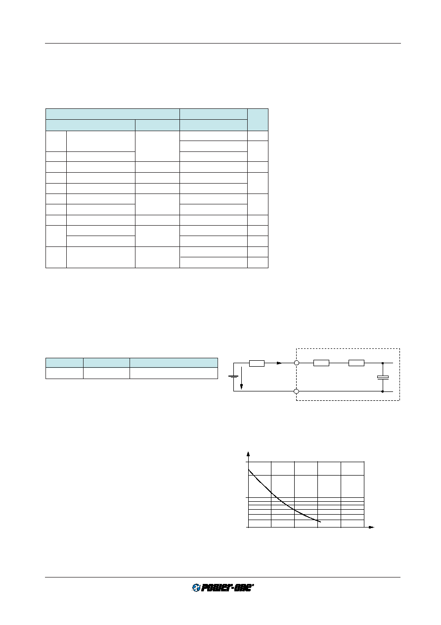
Static Input Current Characteristic
2
345
6
1
1.00
Ui DC
_______
Ui min DC
Ii (A)
3.00
0.40
04048
Fig. 4
Input current versus relative input voltage
Input Fuse
A fuse mounted inside the converter protects the module
against severe defects. If operated from a DC source this
fuse may not fully protect the module when the input volt-
age exceeds 200 V DC! In applications where the convert-
ers operate at source voltages above 200 V DC an external
fuse or a circuit breaker at system level should be installed!
Table 3: Fuse Specification
Module
Fuse type
Fuse rating
LK 1
slow-blow
SPT
4 A, 250 V
1 Fuse size 5
× 20 mm.
Input Under-/Overvoltage Lock-out
If the input voltage remains below approx. 0.8
Ui min or ex-
ceeds approx. 1.1
Ui max, an internally generated inhibit sig-
nal disables the output(s). When checking this function the
absolute maximum input voltage rating
Ui abs should be
considered! Between
Ui min and the undervoltage lock-out
level the output voltage may be below the value defined in
table:
Output data (see: Technical Information: Measuring
and Testing).
Reverse Polarity Protection
The built-in bridge rectifier provides reverse polarity protec-
tion at the input.
Inrush Current Limitation
The modules of the versions -7 incorporate an NTC resistor
in the input circuitry which – at initial turn on – reduces the
peak inrush current value by a factor of 5...10 to protect
connectors and switching devices from damage. Subse-
quent switch-on cycles within short periods will cause an
increase of the peak inrush current value due to the warm-
ing-up of the NTC resistor. (see also:
option E)
Inrush Current Peak Value
The inrush current peak value (initial switch-on cycle) can
be determined by following calculation: (See also:
Input In-
rush Current Characteristic).
Ui source
Iinr p = ––––––––––––––––
(
Rs ext + Ri + RNTC)
Rs ext
Ri
RNTC
Iinr p
Ui source
+
Ci int
04040
Fig. 3
Equivalent circuit diagram for input impedance
Electrical Input Data
General Conditions
–
TA = 25
°C, unless T
C is specified.
– Pin 18 connected to pin 14,
Uo adjusted to Uo nom (option P); R input not connected.
– Sense line pins S+ and S– connected to Vo+ and Vo– respectively.
Table 2: Input data
Input
LK
Characteristics
Conditions
min
typ
max
Unit
Ui
Operating input voltage
Io = 0…Io nom
85
264
V AC
TC min…TC max
88
372
V DC
Ui nom Nominal input voltage
310
3
Ii
Input current
Ui nom, Io nom 1
0.4
A
Pi0
No-load input power
Ui min…Ui max
2.5
W
Pi inh
Idle input power
unit inhibited
1.5
Ri
Input resistance
TC = 25°C
480
m
RNTC
NTC resistance 2
3200
Ci
Input capacitance
210
400
F
Ui RFI
Conducted input RFI
EN 55022
B
Radiated input RFI
Ui nom, Io nom
B
Ui abs
Input voltage limits
–400
400
V DC
without damage
–400
400
Vp
1 With double output modules, both outputs
loaded with
Io nom
2 Valid for -7 versions with NTC, (-9 versions ex-
clude the NTC). Initial switch-on cycle. Subse-
quent switch-on/off cycles increase the inrush
current peak value.
3 LK types may also be operated in DC mode.
(See:
K Series, DC-DC Converters)
AC frequency range 47...440 Hz (440 Hz
for 115 V mains).
Above 70 Hz (at
Ui = 264 V AC) the earth
lekage current may exceed 3.5 mA, speci-
fied in IEC/EN 60950. The built-in Y ca-
pacitors are specified for
≤100 Hz. Above
350 Hz the input voltage may not exceed
200 V AC.
相關(guān)PDF資料 |
PDF描述 |
|---|---|
| LK2320-7ERD2TB2 | 2-OUTPUT 150 W AC-DC REG PWR SUPPLY MODULE |
| LK2320-7RD0TB2 | 2-OUTPUT 150 W AC-DC REG PWR SUPPLY MODULE |
| LK2320-7RD1 | 2-OUTPUT 150 W AC-DC REG PWR SUPPLY MODULE |
| LK2320-7RD3T | 2-OUTPUT 150 W AC-DC REG PWR SUPPLY MODULE |
| LK2320-7RD5T | 2-OUTPUT 150 W AC-DC REG PWR SUPPLY MODULE |
相關(guān)代理商/技術(shù)參數(shù) |
參數(shù)描述 |
|---|---|
| LK2320-7R | 功能描述:線性和開關(guān)式電源 Euro-Cassette 150W (2x 12V) RoHS:否 制造商:TDK-Lambda 產(chǎn)品:Switching Supplies 開放式框架/封閉式:Enclosed 輸出功率額定值:800 W 輸入電壓:85 VAC to 265 VAC 輸出端數(shù)量:1 輸出電壓(通道 1):20 V 輸出電流(通道 1):40 A 商用/醫(yī)用: 輸出電壓(通道 2): 輸出電流(通道 2): 安裝風(fēng)格:Rack 長度: 寬度: 高度: |
| LK2320-7RB1 | 制造商:Power-One 功能描述: |
| LK23207RD7 | 制造商:Power-One 功能描述: |
| LK2320-9ER | 制造商:Power-One 功能描述:AC/DC Power Supply Dual-OUT 12V/12V 6A/6A 150W 15-Pin 制造商:Power-One 功能描述:ACDC - Bulk |
| LK23-LFR | 制造商:FRONTIER 制造商全稱:Frontier Electronics. 功能描述:2A SURFACE MOUNT SCHOTTKY BARRIER RECTIFIERS |
發(fā)布緊急采購,3分鐘左右您將得到回復(fù)。