- 您現(xiàn)在的位置:買賣IC網(wǎng) > PDF目錄358789 > LH1554M LCD Display Driver PDF資料下載
參數(shù)資料
| 型號: | LH1554M |
| 英文描述: | LCD Display Driver |
| 中文描述: | 液晶顯示驅(qū)動程序 |
| 文件頁數(shù): | 41/51頁 |
| 文件大小: | 288K |
| 代理商: | LH1554M |
第1頁第2頁第3頁第4頁第5頁第6頁第7頁第8頁第9頁第10頁第11頁第12頁第13頁第14頁第15頁第16頁第17頁第18頁第19頁第20頁第21頁第22頁第23頁第24頁第25頁第26頁第27頁第28頁第29頁第30頁第31頁第32頁第33頁第34頁第35頁第36頁第37頁第38頁第39頁第40頁當(dāng)前第41頁第42頁第43頁第44頁第45頁第46頁第47頁第48頁第49頁第50頁第51頁

41
LH155BA
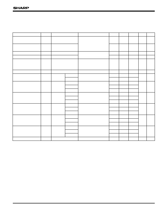
7. ELECTRICAL CHARACTERISTICS
7.1. DC Characteristics
(Unless otherwise specified, V
SS
= 0 V, V
DD
= +1.8 to +5.5 V, T
OPR
= –30 to +85 °C)
SYMBOL
CONDITIONS
APPLICABLE PINS
D
7
-D
0
, CSB, RS, M/S, M86, RDB,
WRB, CK, CKS, OSCI, LP, FLM,
M, SDA, SCL, P/S, RESB, EXA,
PMODE
V
OL
I
OL
= 0.4 mA
D
7
-D
0
, LP, FLM, M
V
OH
I
OH
= –0.4 mA
CSB, RS, M/S, M86, RDB, WRB,
CK, CKS, OSCI, SDA, SCL, P/S,
RESB, EXA, PMODE
I
LO
V
I
= V
SS
or V
DD
D
7
-D
0
, LP, FLM, M
|V
ON
|
= 0.5 V
COM
0
-COM
63
V
0
= 6 V
V
DD
= 5 V
V
DD
= 3 V
V
DD
= 2 V
V
DD
= 5 V
V
DD
= 3 V
V
DD
= 2 V
V
DD
= 5 V
V
DD
, V
EE
hold
mode
During
active mode
fCYC = 100 kHz
V
DD
= 2 V
V
DD
= 5 V
OSCO
680 k$±2%
PARAMETER
MIN.
TYP.
MAX. UNIT NOTE
Input "Low" voltage
V
IL
0
0.2V
DD
V
Input "High" voltage
V
IH
0.8V
DD
V
DD
V
Output "Low" voltage
Output "High" voltage
0.4
V
V
V
DD
– 0.4
Input leakage current
I
LI
V
I
= V
SS
or V
DD
–10
10
μA
Output leakage current
LCD drive output ON
resistance
–10
10
4
6
μA
1
R
ON
V
0
= 10 V SEG
0
-SEG
127
,
k$
2
Standby current
I
STB
CK = 0 V
CSB = V
DD
V
DD
20
10
5
μA
3
Supply current (1)
I
DD1
During
sleep
mode
During
V
DD
20
10
5
240
μA
4
Reset ("L") pulse width
NOTES :
1. Applied when D
7
to D
0
, LP, FLM, and M are in the high
impedance state.
2. Resistance when 0.5 V is applied between each output
pin and each power supply (V
0
, V
1
, V
2
, V
3
, V
4
). Applied
when power is supplied at power bias ratio of 1/9 in the
external power supply mode.
3. Current at the V
DD
pin when the master clock stops, the
chip is not selected (CSB = V
DD
), and no load is used.
All circuits stop.
4. Sleep mode supply current.
Stop internal oscillation clock, using external EXA signal.
Without using booster circuits. Graphic and segment
displays OFF. Icon display ON. No load.
t
RW
RESB
10
μs
5. Applied when no access is made by the MPU when the
internal oscillation circuit (R
F
= 680 k$) and power
supply circuit (PMODE = "L") are used. The electronic
volume is preset (the code is "1 1 1 1"). The display is
OFF and the LCD drive pin is not loaded.
Measuring conditions : V
DD
= V
EE
, V
R1
= V
R2
, C
1
= C
2
=
1 μF, R
1
+ R
2
+ R
3
= 4 M$.
6. Active mode supply current.
Using internal oscillation clock.
Writing at f
CYC
the graphic display data which are
reversed every one bit. No load.
7. Oscillation frequency when connecting a feedback
resistor (R
F
) of 680 k$ between OSCI and OSCO.
80
120
V
DD
= 2 V
V
DD
= 5 V
V
DD
= 3 V
V
DD
= 3 V
5
μA
I
DD2
Supply current (2)
Supply current (3)
I
DD3
V
DD
1 200
400
200
μA
6
24
28
V
DD
= 2 V
V
DD
= 3 V
7
kHz
30
R
F
=
f
OSC
Oscillation frequency
相關(guān)PDF資料 |
PDF描述 |
|---|---|
| LH1560F | 160 OUTPUT LCD SEGMENT / COMMON DRIVER |
| LH15A1 | LCD driver with built-in RAM for 256-color STN-LCDs |
| LH1684F | 5 V Drive 240 Outputs TFT-LCD Source Driver |
| LH1687 | 240-output TFT-LCD Source Driver IC |
| LH168A | 384-output TFT-LCD Source Driver IC |
相關(guān)代理商/技術(shù)參數(shù) |
參數(shù)描述 |
|---|---|
| LH1554P | 制造商:未知廠家 制造商全稱:未知廠家 功能描述:LCD Display Driver |
| LH15550 | 制造商:TE Connectivity 功能描述: |
| LH1556AAC | 功能描述:固態(tài)繼電器-PCB安裝 Dual Normally Open Form 1A 350V RoHS:否 制造商:Omron Electronics 控制電壓范圍: 負(fù)載電壓額定值:40 V 負(fù)載電流額定值:120 mA 觸點形式:1 Form A (SPST-NO) 輸出設(shè)備:MOSFET 封裝 / 箱體:USOP-4 安裝風(fēng)格:SMD/SMT |
| LH1556AAC_11 | 制造商:VISHAY 制造商全稱:Vishay Siliconix 功能描述:Dual 1 Form A Solid-State Relay |
| LH1556AACTR | 功能描述:固態(tài)繼電器-PCB安裝 Dual Normally Open Form 1A 350V RoHS:否 制造商:Omron Electronics 控制電壓范圍: 負(fù)載電壓額定值:40 V 負(fù)載電流額定值:120 mA 觸點形式:1 Form A (SPST-NO) 輸出設(shè)備:MOSFET 封裝 / 箱體:USOP-4 安裝風(fēng)格:SMD/SMT |
發(fā)布緊急采購,3分鐘左右您將得到回復(fù)。