- 您現(xiàn)在的位置:買賣IC網 > PDF目錄358788 > LH1530 (SIEMENS AG) High Voltage Solid State Relays PDF資料下載
參數(shù)資料
| 型號: | LH1530 |
| 廠商: | SIEMENS AG |
| 英文描述: | High Voltage Solid State Relays |
| 中文描述: | 高壓固態(tài)繼電器 |
| 文件頁數(shù): | 8/20頁 |
| 文件大小: | 176K |
| 代理商: | LH1530 |
Absolute Maximum Ratings
T
A
=25
°
C
Stresses in excess of the Absolute Maximum Ratings can cause permanent damage to the device. These are
absolute stress ratings only. Functional operation of the device is not implied at these or any other conditions in
excess of those given in the operational sections of this document. Exposure to Absolute Maximum Ratings for
extended periods of time can adversely affect reliability.
LH1517, LH1518, LH1519
1 Form A
* 5300 Vrms input/output isolation voltage available on some products. Consult factory.
Refer to Current-Limit Performance Application Note for a discussion on relay operation during transient currents.
Parameter
Symbol
Test Conditions
LH1517
LH1518
LH1519
Units
Ambient Operating
Temperature range
Storage Temperature Range
Pin Soldering Temperature
Input/Output Isolation Voltage*
LED Continuous Forward
Current
LED Reverse Voltage
dc or Peak ac Load Voltage
Continuous dc Load Current
Bidirectional Operation
Unidirectional Operation
Peak Load Current
T
A
—
–40 to +85
°
C
T
stg
T
S
V
ISO
I
F
–40 to +150
260
3750
50
t=10 s max
—
Vrms
mA
V
R
V
L
I
L
I
R
£
10
m
A
I
L
£
50
m
A
8
V
150
250
—
400
800
1200
155
300
240
450
mA
I
P
t=100 ms
(single shot)
Output Power Dissipation
(continuous)
P
DISS
—
600
550
mW
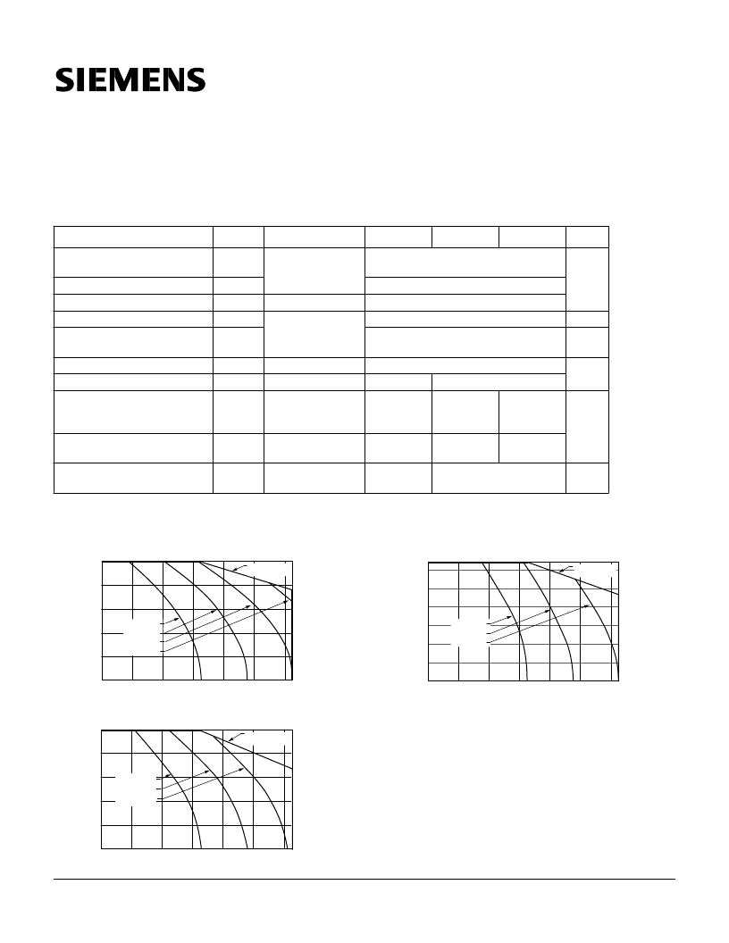
Recommended Operating Conditions
AMBIENT TEMPERATURE (
°
C)
L
320
240
160
0
400
80
–40
–20
0
20
40
60
80
FON
=
I
LH1517
I
FON
= 2 mA
I
FON
= 3 mA
I
FON
= 4 mA
I
FON
= 5 mA
135
90
–40
–20
0
20
40
60
80
AMBIENT TEMPERATURE (
°
C)
L
0
45
225
180
LH1519
FON
=
I
I
FON
= 3 mA
I
FON
= 3 mA
I
FON
= 2 mA
120
60
40
0
130
20
100
80
–40
–20
0
20
40
60
80
AMBIENT TEMPERATURE (
°
C)
L
LH1518
FON
=
I
I
FON
= 2 mA
I
FON
= 3 mA
I
FON
= 4 mA
Siemens Microelectronics, Inc. Optoelectronics Division
www.smi.siemens.com/opto/
8 of 20
October 1998
相關PDF資料 |
PDF描述 |
|---|---|
| LH1532AAC | Dual 1 Form A Solid State Relay |
| LH1532 | Device is not Implied at these or any Other conditions in Excess |
| LH1532AACTR | Dual 1 Form A Solid State Relay |
| LH1532AB | Dual 1 Form A Solid State Relay |
| LH1532FP | Dual 1 Form A Dual 1 Form A |
相關代理商/技術參數(shù) |
參數(shù)描述 |
|---|---|
| LH1530AAB | 制造商:未知廠家 制造商全稱:未知廠家 功能描述: |
| LH1530AT | 制造商:未知廠家 制造商全稱:未知廠家 功能描述: |
| LH1530F | 制造商:未知廠家 制造商全稱:未知廠家 功能描述:LCD Display Driver |
| LH1531 | 制造商:INFINEON 制造商全稱:Infineon Technologies AG 功能描述:Device is not Implied at these or any Other conditions in Excess |
| LH1531AAC | 制造商:Vishay Semiconductors 功能描述:SOLID STATE RELAY, 8 PIN DUAL, - Bulk 制造商:TE Connectivity 功能描述: |
發(fā)布緊急采購,3分鐘左右您將得到回復。