- 您現(xiàn)在的位置:買賣IC網(wǎng) > PDF目錄358787 > LH1505AB (Vishay Intertechnology,Inc.) Dual 1 Form A Solid State Relay PDF資料下載
參數(shù)資料
| 型號: | LH1505AB |
| 廠商: | Vishay Intertechnology,Inc. |
| 英文描述: | Dual 1 Form A Solid State Relay |
| 中文描述: | 雙1 A型固態(tài)繼電器 |
| 文件頁數(shù): | 2/5頁 |
| 文件大小: | 89K |
| 代理商: | LH1505AB |
Document Number: 83809
Revision 17-August-01
www.vishay.com
3–52
Electrical Characteristics,
Minimum and maximum values are testing requirements. Typical values are characteristics of the device and are the result of
engineering evaluations. Typical values are for information only and are not part of the testing requirements.
T
A
=25
°
C
*
I
L
=100 mA
Parameter
Sym.
Min.
Typ.
Max.
Units
Test Conditions
Input
LED Forward Current, Switch Turn-on
I
Fon
—
1.0
2.0
mA
I
L
=100 mA, t=10 ms
LED Forward Current, Switch Turn-off
I
Foff
V
F
0.2
0.9
—
mA
V
L
=10 mA
±200 V
LED Forward Voltage
1.15
1.26
1.45
V
I
F
Output
ON-resistance
R
ON
10
15
20
I
F
=5.0 mA,
I
L
=±100 V
=50 mA
OFF-resistance
R
OFF
0.5
5000
—
G
I
F
=0 mA,
V
L
Current Limit
I
LMT
170
200
280
mA
I
V
F
=5.0 mA, t=5.0 ms
L
±6.0 V
=0 mA,
V
Off-state Leakage Current
—
—
0.02
200
nA
I
F
L
=±100 V
—
—
1.0
μ
A
I
F
=0 mA,
V
L
=±250 V
Output Capacitance
—
—
55
—
pF
I
F
=0 mA,
V
L
=1.0 V
—
10
—
I
F
=0 mA,
V
L
=50 V
Pole-to-Pole Capacitance (S1 to S2)
—
—
0.5
—
pF
I
F
=5.0 mA
Switch Offset
—
—
0.15
—
V
I
F
=5.0 mA
Transfer
Input/Output Capacitance
C
ISO
—
1.1
—
pF
V
ISO
=5.0 mA,
=1.0 V
Turn-on Time
t
on
t
off
—
1.4*
4.0*
ms
I
F
I
L
=50 mA
Turn-off Time
—
0.7*
4.0*
ms
I
F
=5.0 mA,
I
L
=50 mA
Absolute Maximum Ratings,
Stresses in excess of the Absolute Maximum Ratings can cause permanent
damage to the device. These are absolute stress ratings only. Functional opera-
tion of the device is not implied at these or any other conditions in excess of
those given in the operational sections of the data sheet. Exposure to maximum
rating conditions for extended periods can adversely affect device reliability.
T
A
=25
°
C
Ambient Temperature Range (
Storage Temperature Range (
Pin Soldering Temperature (t=10 s max) (
Input/Output Isolation Voltage
(t=1.0 s,
I
ISO
=10
μ
A max) (
Pole-to-Pole Isolation Voltage (S1 to S2)*
(dry air, dust free, at sea level).................................................1600 V
LED Continuous Forward Current (
I
LED Reverse Voltage (
I
R
≤
10
μ
A) (
V
DC or Peak AC Load Voltage (
I
L
≤
50
Continuous DC Load Current (
I
L
)
One Pole Operating.................................................................130 mA
Two Poles Operating ...............................................................120 mA
Peak Load Current (t=100 ms) (single shot) (
Output Power Dissipation (continuous) (
T
T
A
stg
)....................................–40 to +85
).................................–40 to +150
T
S
) .............................260
°
°
°
C
C
C
V
ISO
)....................................... 5300 V
RMS
F
R
).........................................50 mA
)...........................................8.0 V
μ
A) (
V
L
)..............................250 V
I
P
)........................600 mW
).................................
P
DISS
*
Refer to Current Limit Performance Application Note for a discussion on
relay operation during transient currents.
Breakdown occurs between the output pins external to the package.
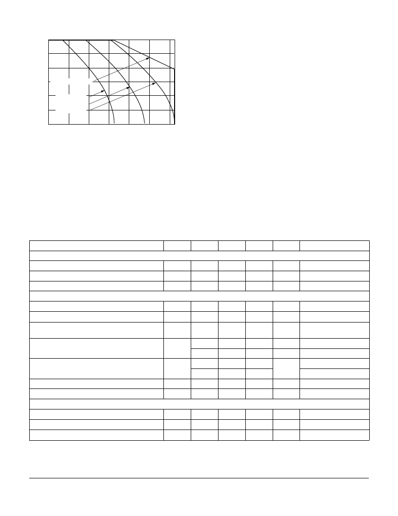
Recommended Operating Conditions
120
60
80
0
–
40
–
20 0 20 40 60 80
Ambient Temperature (
°
C)
40
100
20
L
I
Fon
=2.0 mA
I
Fon
=3.0 mA
I
Fon
=4.0 mA
I
Fon
=5.0 to 20 mA
相關PDF資料 |
PDF描述 |
|---|---|
| LH1505 | Device is not Implied at these or any Other conditions in Excess |
| LH1510AAB | 1 Form A Solid State Relay |
| LH1510AABTR | 1 Form A Solid State Relay |
| LH1510AT | 1 Form A Solid State Relay |
| LH1511BAB | 1 Form B Solid State Relay |
相關代理商/技術參數(shù) |
參數(shù)描述 |
|---|---|
| LH1505AB_11 | 制造商:VISHAY 制造商全稱:Vishay Siliconix 功能描述:Dual 1 Form A Solid-State Relay |
| LH1505-CK | 制造商:Black Box Corporation 功能描述:Dual-Source Cable Kit |
| LH1505-CK-W1 | 制造商:Black Box Corporation 功能描述:1 YEAR WARRANTY FOR LH1505-CK |
| LH1505-CK-W3 | 制造商:Black Box Corporation 功能描述:3 YEAR WARRANTY FOR LH1505-CK |
| LH1505P-RACK | 制造商:Black Box Corporation 功能描述:Rackmount Tray for LBHxxxA, LE15xxA, and LP004A Series, with (1) 9-V Power Suppl |
發(fā)布緊急采購,3分鐘左右您將得到回復。