- 您現(xiàn)在的位置:買賣IC網(wǎng) > PDF目錄361022 > LH0091 (National Semiconductor Corporation) LH0091 True RMS to DC Converter PDF資料下載
參數(shù)資料
| 型號: | LH0091 |
| 廠商: | National Semiconductor Corporation |
| 英文描述: | LH0091 True RMS to DC Converter |
| 中文描述: | LH0091真有效值直流轉換器 |
| 文件頁數(shù): | 5/6頁 |
| 文件大?。?/td> | 126K |
| 代理商: | LH0091 |
Typical Applications
(Continued)
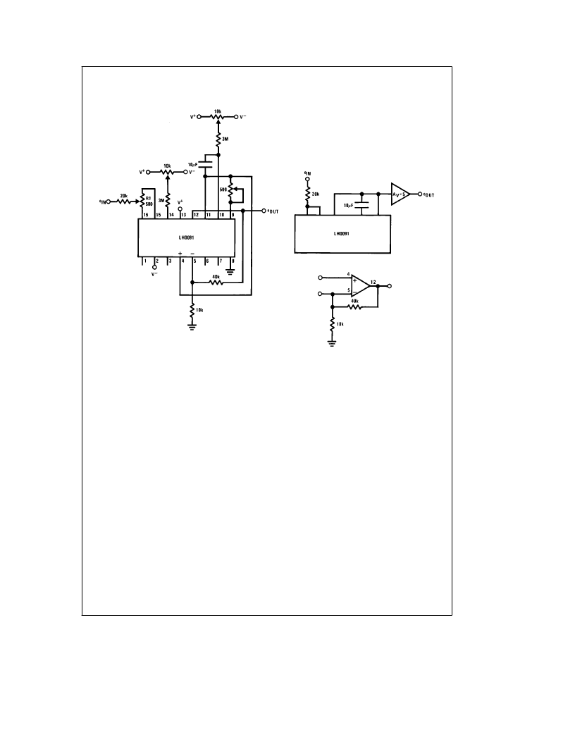
Note. When converting signals with a crest factor
t
2, the LH0091 should
be connected as shown. Note that this circuit utilizes a 20k resistor to drop
the input current by a factor of five. The frequency response will correspond
to a voltage which is 1/5 e
IN
.
Note that the extra op amp in the LH0091 may be used to build a gain of 5
amplifier to restore the output voltage.
TL/H/5694–7
Note. Response time of the dc output voltage is dominated
by the RC time constant consisting of the total resistance
between pins 9 and 10 and the external capacitor, C
EX
.
FIGURE 5. High Crest Factor Circuit
Definition of Terms
True rms to dc Converter:
A device which converts any
signal (ac, dc, ac
a
dc) to the dc equivalent of the rms value.
Error:
is the amount by which the actual output differs from
the theoretical value. Error is defined as a sum of a fixed
term and a percent of reading term. The fixed term remains
constant, regardless of input while the percent of reading
term varies with the input.
Total Unadjusted Error:
The total error of the device with-
out any external adjustments.
Bandwidth:
The frequency at which the output dc voltage
drops to 0.707 of the dc value at low frequency.
Frequency for Specified Error:
The error at low frequency
is governed by the size of the external averaging capacitor.
At high frequencies, error is dependent on the frequency
response of the internal circuitry. The frequency for speci-
fied error is the maximum input frequency for which the out-
put will be within the specified error band (i.e., frequency for
1% error means the input frequency must be less than 200
kHz to maintain an output with an error of less than 1% of
the initial reading.
Crest Factor:
is the peak value of a waveform divided by
the rms value of the same waveform. For high crest factor
signals, the performance of the LH0091 can be improved by
using the high crest factor connection.
5
相關PDF資料 |
PDF描述 |
|---|---|
| LH0094 | Multifunction Converter |
| LH0094CD | Multifunction Converter |
| LH4001 | Wideband Current Buffer |
| LH4001CN | Wideband Current Buffer |
| LM1035 | DUAL DC OPERATED TONE/VOLUME BALANCE CIRCUITS |
相關代理商/技術參數(shù) |
參數(shù)描述 |
|---|---|
| LH0091D | 制造商:未知廠家 制造商全稱:未知廠家 功能描述:RMS-to-DC Converter |
| LH0094 | 制造商:NSC 制造商全稱:National Semiconductor 功能描述:Multifunction Converter |
| LH0094CD | 制造商:NSC 制造商全稱:National Semiconductor 功能描述:Multifunction Converter |
| LH0094D | 制造商:未知廠家 制造商全稱:未知廠家 功能描述:Analog Multiplier/Divider |
| LH0094D/883 | 制造商:未知廠家 制造商全稱:未知廠家 功能描述:Analog Multiplier/Divider |
發(fā)布緊急采購,3分鐘左右您將得到回復。