- 您現(xiàn)在的位置:買賣IC網(wǎng) > PDF目錄377623 > LEE-59 (MINI-CIRCUITS) Surface Mount Monolithic Amplifiers PDF資料下載
參數(shù)資料
| 型號(hào): | LEE-59 |
| 廠商: | MINI-CIRCUITS |
| 元件分類: | 衰減器 |
| 英文描述: | Surface Mount Monolithic Amplifiers |
| 中文描述: | 0 MHz - 5000 MHz RF/MICROWAVE WIDE BAND LOW POWER AMPLIFIER |
| 封裝: | CASE FG873, 4 PIN |
| 文件頁(yè)數(shù): | 1/2頁(yè) |
| 文件大小: | 144K |
| 代理商: | LEE-59 |
INTERNET
http://www.minicircuits.com
P
.
O
.
B
o
x
350166,
B
roo
kly
n
,
Ne
w
Y
or
k
11235-0003
(718)
934-4500
Fax
(718)
332-4661
Distribution Centers
NO
RTH
AMERICA
800-654-7949
417-335-5935
Fax
417-335-5945
E
U
R
OP
E
44-1252-832600
Fax
44-1252-837010
Mini-Circuits
I
SO 9001 C
ERTI
F
IE
D
REV. D
M90145
LEE-19
LEE-29
LEE-39
LEE-49
LEE-59
RS/YB/LC
031210
Page 1 of 2
ED-10757/1
ED-10757/2
ED-10757/3
ED-10757/4
ED-10757/5
Features
frequency range, DC to 8 GHz, useable to 10 GHz
up to 17.3 dBm typ. output power
excellent package for heat dissipation, exposed metal bottom
flat output power to 10 GHz (LEE-19,-29,-39)
Applications
cellular
PCS
communication receivers & transmitters
satellite communication, military
50
, Broadband,
DC to 8 GHz
Electrical Specifications @ 25°C
Maximum Ratings
Operating Temperature
Storage Temperature
-45°C to 85°C
-65°C to 150°C
FREQ.
(GHz)
s
MODEL
NO.
RF IN
RF OUT
DC
GND EXT.
DEMO BOARD
1
3
3
2,4
LEE-TB
f
L
- f
U
DC OPERATING
POWER
@Pin 3
(note 4)
Cur-
rent
(mA)
Typ Min Max
VSWR
(:1)
Typ.
DYNAMIC
RANGE
NF
dB
Typ.
IP3
dBm
Typ.
MAXIMUM
POWER, dBm
Input
(no
dmg.)
Output
(1dB Comp.)
2 GHz
1
0.1
Min. @
2GHz
GAIN, dB Typical
over frequency, GHz
2
Low Power
12.1 12.0 12.1 12.0 11.6 10.6
15.5 15.4 15.4 14.9 14.1 12.5
21.9 21.4 20.8 18.3 16.6 13.5
Medium Power
14.0 13.9 14.3 14.0 13.1
20.6 20.3 19.7 15.8 13.8
4
5
8
10
MAXIMUM
CURRENT
RATING
3
Out
DC-3
GHz
3-f
U
GHz
THERMAL
RESIS-
TANCE
θ
jc,
typ.
°C/W
In
Volt
I
mA
DC-3
GHz
PRICE
$
Qty.
(25)
3-f
U
GHz
f
U
is the upper frequency limit for each model as shown in the table.
s
Low frequency cutoff determined by external coupling capacitors.
3 Permanent damage may occur if any of these limits are exceeded.
These ratings are not intended for continuous normal operation.
4. Supply voltage must be connected to pin 3 through a bias resistor in order to
prevent damage. See "Biasing MMIC Amplifiers" in minicircuits.com/
application.html. Reliability predictions are applicable at specified current &
normal operating conditions.
Model Identification
Model
LEE-19
LEE-29
LEE-39
LEE-49
LEE-59
Marking
19
29
39
49
59
Pin Configuration
Prefix letter (optional) designates assembly location.
Suffix letters (optional) are for wafer identification.
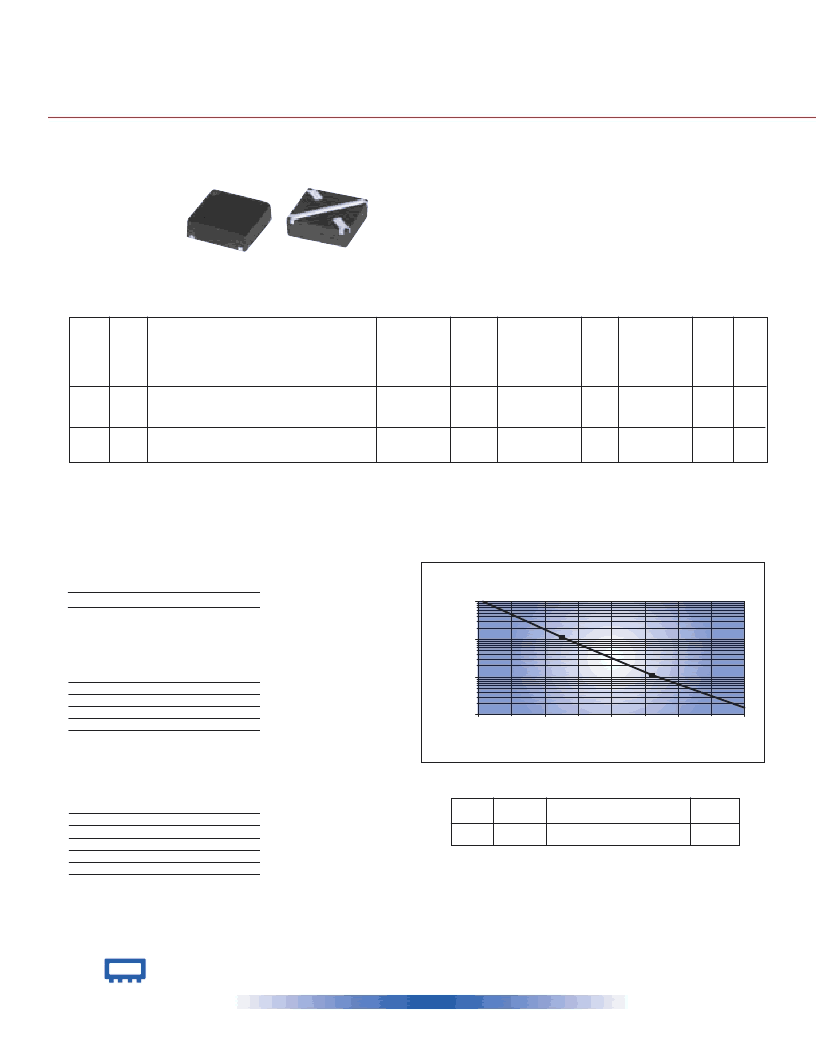
CASE STYLE : FG873
1
1
4
0
1
0
1
00
1
,
000
M
(
1
6
0
1
8
0
2
00
22
0
Junction
Te
mp
(
C
)
MTTF vs. Junction Temp.
(LEE-19,-29,-39,-49,-59)
f
U
LEE-19
LEE-29
LEE-39
DC-8
DC-8
DC-8
9.0
10.6
10.5
9.6
13.3
18.5
10.2 11.3
10.9 11.3
10.4 11.3
15
15
13
6.5
5.5
4.5
24.5
25.5
23.4
1.5
1.4
1.3
1.2
1.3
1.4
1.4
1.3
1.3
1.8
1.6
1.6
55
55
55
40
40
35
3.6 3.2 4.0
3.6 3.2 4.0
3.5 3.1 3.9
322
334
321
1.19
1.19
1.19
LEE-49
LEE-59
DC-5
DC-5
7.8
7.6
—
—
12.0
17.8
16.4 10.8
17.3 11.7
15
13
5.5
4.5
33
33
1.6
1.5
1.2
1.5
1.4
1.5
1.4
1.6
85
85
65
65
4.9 4.5 5.3
4.8 4.3 5.2
229
244
1.79
1.79
NEW!
LEE-19 LEE-29 LEE-39
LEE-49 LEE-59
KIT
No.
K1-LEE
No. of
Units in KIT
50
Description
designers kits available
Price $
per KIT
99.95
Kit includes 1 test board plus
10 of each: LEE-19,-29,-39,-49,-59
Monolithic Amplifiers
SuraceMoun
相關(guān)PDF資料 |
PDF描述 |
|---|---|
| LESDA14V2LT1G | Dual transil array for ESD protection |
| LESDA25LT1G | Dual transil array for ESD protection |
| LESDA5V3LT1G | Dual transil array for ESD protection |
| LESDA6V1LT1G | Dual transil array for ESD protection |
| LESDAXXXLT1G | Dual transil array for ESD protection |
相關(guān)代理商/技術(shù)參數(shù) |
參數(shù)描述 |
|---|---|
| LEE9011E-UK-W1 | 制造商:Black Box Corporation 功能描述:1 YEAR WARRANTY FOR LEE9011E-UK |
| LEE9011E-UK-W3 | 制造商:Black Box Corporation 功能描述:3 YEAR WARRANTY FOR LEE9011E-UK |
| LEE9011E-W1 | 制造商:Black Box Corporation 功能描述:1 YEAR WARRANTY FOR LEE9011E |
| LEE9011E-W3 | 制造商:Black Box Corporation 功能描述:3 YEAR WARRANTY FOR LEE9011E |
| LEE9042E | 制造商:Black Box Corporation 功能描述:10/100 SECURE DEV SRV 2 PT RS232/422/485 RJ45 |
發(fā)布緊急采購(gòu),3分鐘左右您將得到回復(fù)。