- 您現(xiàn)在的位置:買賣IC網(wǎng) > PDF目錄358763 > LC75410E (Sanyo Electric Co.,Ltd.) Electronic Volume Controller for Car Audio Systems PDF資料下載
參數(shù)資料
| 型號: | LC75410E |
| 廠商: | Sanyo Electric Co.,Ltd. |
| 英文描述: | Electronic Volume Controller for Car Audio Systems |
| 中文描述: | 電子汽車音響系統(tǒng)的音量控制器 |
| 文件頁數(shù): | 22/28頁 |
| 文件大小: | 234K |
| 代理商: | LC75410E |
第1頁第2頁第3頁第4頁第5頁第6頁第7頁第8頁第9頁第10頁第11頁第12頁第13頁第14頁第15頁第16頁第17頁第18頁第19頁第20頁第21頁當前第22頁第23頁第24頁第25頁第26頁第27頁第28頁
Usage Cautions
(1) Data transmission at power ON
The status of internal analog switches is unstable at power ON. Therefore, perform muting or some other
countermeasure until the data has been set.
At power ON, initial setting data must be sent once in order to stabilize the bias of each block in a short time.
(2) Description of zero-cross switching circuit operation
The LC75410E and 75410W have a function to switch zero-cross comparator signal detection locations, enabling the
selection of the optimum detection location for blocks whose data is to be updated. Basically, the switching noise can
be minimized by inputting the signal immediately following the block whose data is to be updated to the zero-cross
comparator, so it is necessary to switch the detection location every time.
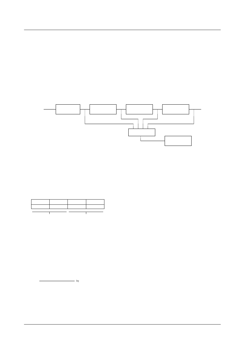
LC75410E, 75410W Zero-Cross Detection Circuit
No. 7027-22/28
LC75410E, 75410W
Volume
Tone
Switch
Fader
Zero-cross
comparator
Selector
(3) Zero-cross switching control method
The zero-cross switching control method consists of setting the zero-cross control bits to the zero-cross detection
mode (D36, D37 = 0), and specifying the detection blocks (D38, D39) before transmitting the data. These control bits
are latched immediately following data transfer, that is to say beforehand in sync with the falling edge of CE, so when
updating data of volumes, etc., it is possible to perform mode setting and zero-cross switching with one data transfer.
An example of control when updating the data of the volume block is shown below.
Zero-cross detection
mode setting
Volume block
setting
D36
D37
D38
D39
0
0
1
0
(4) Zero-cross timer setting
If the input signal becomes lower than the zero-cross comparator detection sensitivity, or if only low-frequency
signals are input, zero-cross detection continues to be impossible, and data is not latched during this time.
The zero-cross timer can set a time for forcible latch during such a status when zero-cross detection is not possible.
For example, to set 25 ms,
using T = 0.69CR and C = 0.033 μF,
we obtain
Normally, a value between 10 ms and 50 ms is set.
R=
1.1 M
25
×
10
–3
0.69
×
0.033
×
10
–6
相關(guān)PDF資料 |
PDF描述 |
|---|---|
| LC75412E | Electronic Volume Controller for Car Audio Systems |
| LC75421 | Electronic Volume Controller for Cars |
| LC75421M | Electronic Volume Controller for Cars |
| LC7565 | FLT Driver for Display of Graphic Equalizer |
| LC7565A | FLT Driver for Display of Graphic Equalizer |
相關(guān)代理商/技術(shù)參數(shù) |
參數(shù)描述 |
|---|---|
| LC75410ES-E | 功能描述:多媒體雜項 RoHS:否 制造商:Texas Instruments 類型: 通道數(shù)量: 轉(zhuǎn)換速率:540 Mbps 分辨率: 封裝 / 箱體:SOIC-16 封裝:Tube |
| LC75410NES-E | 制造商:ON Semiconductor 功能描述:ELECTRONIC VOLUME - Trays |
| LC75410W | 制造商:SANYO 制造商全稱:Sanyo Semicon Device 功能描述:Electronic Volume Controller for Car Audio Systems |
| LC75410WS-E | 功能描述:多媒體雜項 RoHS:否 制造商:ON Semiconductor 類型: 通道數(shù)量: 轉(zhuǎn)換速率: 分辨率: 封裝 / 箱體: 封裝: |
| LC75411ES | 制造商:未知廠家 制造商全稱:未知廠家 功能描述: |
發(fā)布緊急采購,3分鐘左右您將得到回復。