- 您現(xiàn)在的位置:買賣IC網(wǎng) > PDF目錄367537 > LC74735W PDF資料下載
參數(shù)資料
| 型號: | LC74735W |
| 文件頁數(shù): | 42/50頁 |
| 文件大小: | 175K |
| 代理商: | LC74735W |
第1頁第2頁第3頁第4頁第5頁第6頁第7頁第8頁第9頁第10頁第11頁第12頁第13頁第14頁第15頁第16頁第17頁第18頁第19頁第20頁第21頁第22頁第23頁第24頁第25頁第26頁第27頁第28頁第29頁第30頁第31頁第32頁第33頁第34頁第35頁第36頁第37頁第38頁第39頁第40頁第41頁當前第42頁第43頁第44頁第45頁第46頁第47頁第48頁第49頁第50頁
Operational Description
Command transfer method
Overview
(1) Commands are transferred in 8-bit units, LSB first.
Always send a first byte and a second byte (16 bits).
(2) Command 10 (Main RAM write)
Command 11 (Wallpaper write)
Command 71 (Color table write)
When these commands specify continuous mode (RM2, 1 RM3), the IC is locked in continuous write mode.
(Continuous write mode is cleared by setting the CS pin high.)
Writing data to VRAM
(1) Write start address specification
Use command 00 to set the write start address.
V3:0: Vertical direction, H5:0: Horizontal direction
(2) Data write
Continuous write mode differs depending on the write mode specification. (RM1, RM2)
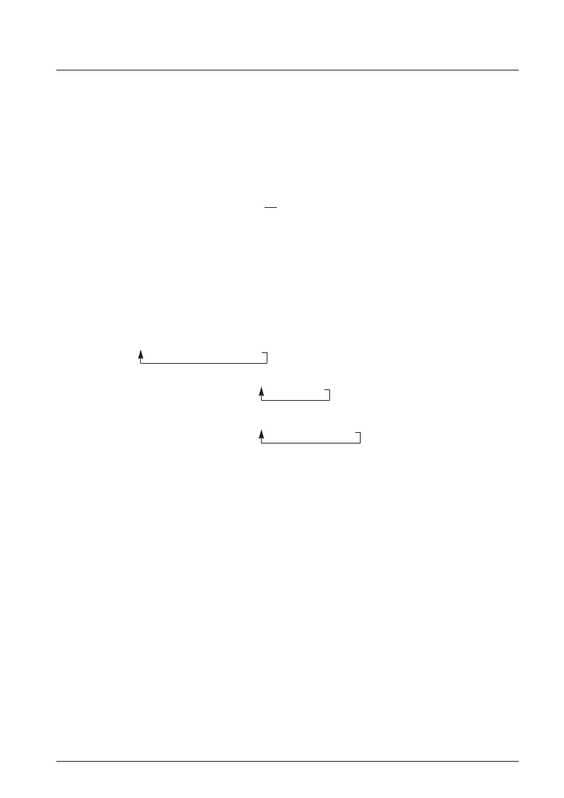
1. Normal (RM2 = 0, RM1 = 0: initial state) *Continuous mode not used*
-- COM10-1 10-2-1 10-2-2 10-2-3 10-2-4 command wait state --
2. Write continuous (RM2 = 0, RM1 = 1): Mode 2
COM10-1 10-2-1 10-2-2 10-2-3 10-2-4
3. Write continuous (RM2 = 1, RM1 = 0): Mode 3
COM10-1 10-2-1 10-2-2 10-2-3 10-2-4 10-2-3 10-2-4
4. Write continuous (RM2 = 1, RM1 = 1): Mode 4
COM10-1 10-2-1 10-2-2 10-2-3 10-2-4 10-2-2 10-2-3 10-2-4
*: In modes 2, 3, and 4, the IC remains locked in continuous write mode until the CS pin is set high.
The write address is automatically incremented.
The write address is retained unless the IC is reset or a new write address is issued.
No. 7191-42/50
LC74735W
相關(guān)PDF資料 |
PDF描述 |
|---|---|
| LC74788N | |
| LC74980W | |
| LC74981W | |
| LC74982W | |
| LC74HC05 | |
相關(guān)代理商/技術(shù)參數(shù) |
參數(shù)描述 |
|---|---|
| LC74736PT | 制造商:SANYO 制造商全稱:Sanyo Semicon Device 功能描述:CMOS IC On-Screen Display Controller |
| LC74736PT_11 | 制造商:SANYO 制造商全稱:Sanyo Semicon Device 功能描述:On-Screen Display Controller |
| LC74736PT-E | 功能描述:顯示驅(qū)動器和控制器 RoHS:否 制造商:Panasonic Electronic Components 工作電源電壓:2.7 V to 5.5 V 最大工作溫度: 安裝風格:SMD/SMT 封裝 / 箱體:QFN-44 封裝:Reel |
| LC7475 | 制造商:SANYO 制造商全稱:Sanyo Semicon Device 功能描述:On-screen Display Controller for PAL-format Video |
| LC74751 | 制造商:SANYO 制造商全稱:Sanyo Semicon Device 功能描述:On-Screen Display LSI |
發(fā)布緊急采購,3分鐘左右您將得到回復(fù)。