- 您現(xiàn)在的位置:買賣IC網(wǎng) > PDF目錄30732 > LC7442 PICTURE-IN-PICTURE IC, PDIP64 PDF資料下載
參數(shù)資料
| 型號(hào): | LC7442 |
| 元件分類: | 畫面疊加 |
| 英文描述: | PICTURE-IN-PICTURE IC, PDIP64 |
| 封裝: | SDIP-64 |
| 文件頁(yè)數(shù): | 6/23頁(yè) |
| 文件大小: | 317K |
| 代理商: | LC7442 |
第1頁(yè)第2頁(yè)第3頁(yè)第4頁(yè)第5頁(yè)當(dāng)前第6頁(yè)第7頁(yè)第8頁(yè)第9頁(yè)第10頁(yè)第11頁(yè)第12頁(yè)第13頁(yè)第14頁(yè)第15頁(yè)第16頁(yè)第17頁(yè)第18頁(yè)第19頁(yè)第20頁(yè)第21頁(yè)第22頁(yè)第23頁(yè)

LC7442, 7442E
Specifications
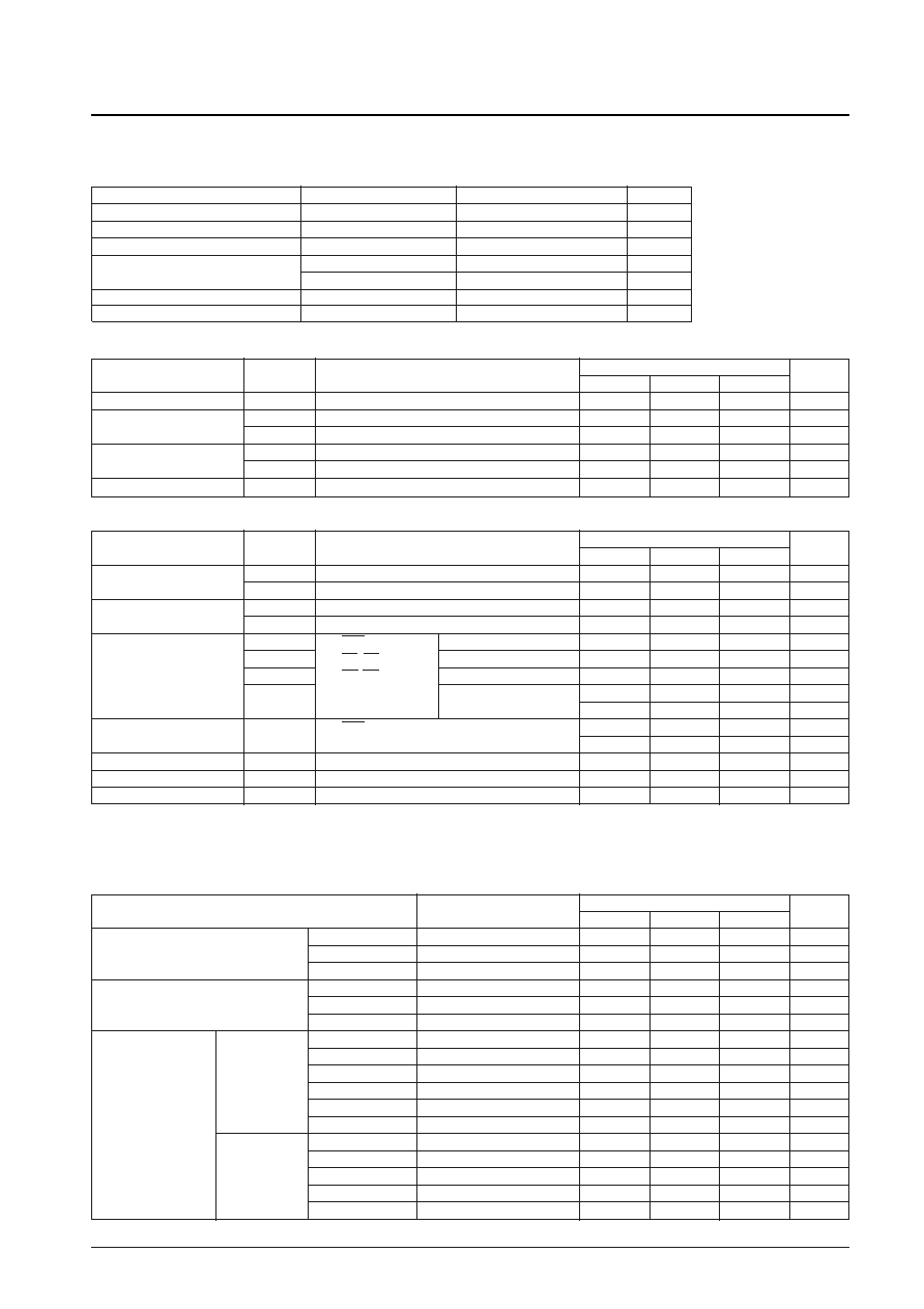
Absolute Maximum Ratings at Ta = 25 ±2°C, VSS = 0 V
Paramater
Symbol
Ratings
Unit
Maximum supply voltage
VDD max
–0.3 to +7.0
V
Maximum input voltage
VIN max
–0.3 to VDD + 0.3
V
Maximum output voltage
VOUT max
–0.3 to VDD + 0.3
V
Allowable power dissipation
Pd1 max (DIP version)
500
mW
Pd2 max (QFP version)
350
mW
Operating temperature
Topr
–10 to +70
°C
Storage temperature
Tstg
–55 to +125
°C
Allowable Operating Ranges at Ta = –10 to +70°C, VSS = 0 V
Ratings
Paramater
Symbol
Conditions
min
typ
max
Unit
Power supply voltage
VDD
4.5
5.0
5.5
V
Input high level voltage
VIH1
CMOS levels
0.7 VDD
V
VIH2
TTL levels
2.2
V
Input low level voltage
VIL1
CMOS levels
0.3 VDD
V
VIL2
TTL levels
0.8
V
Reference voltage
VREF
VREF pin
3.4
0.8 VDD
VDD
V
Electrical Characteristics at Ta = 25 ±2°C, VDD = 5 V ±10%, VSS = 0 V
Ratings
Paramater
Symbol
Conditions
min
typ
max
Unit
Output high level voltage
VOH1
IOH = –1 mA; Pins KCP and OCP
VDD – 1
V
VOH2
IOH = –1 mA; Pins other than KCP and OCP
VDD – 1
V
Output low level voltage
VOL1
IOL = 1 mA; Pins KCP and OCP
1.0
V
VOL2
IOL = 2 mA; Pins other than KCP and OCP
0.4
V
Operating current dissipation
IDDD
RES: H
The DVSS pin
20
mA
IDDA
OV, KV: 60 Hz
The AVSS pin
21
mA
IDDO
OH, KH: 15 kHz
The OVSS pin
2
mA
IDDK
A/D data: 1010
The KVSS pin
2
mA
Output unloaded
Static current dissipation
IDDS
RES: L,
10
A
Input pin DC, output unloaded
Input leakage current
ILK
VI = VDD, VSS
–1
1
A
Output leakage current
IOZ
VI = VDD, VSS; Pins KCP and OCP
–1
1
A
D/A output resistance
RDA
150
Note: There are 4 power supply pin systems.
The power supplies are DVDD, AVDD, OVDD, and KVDD, and they must be identical. Descriptions are for VDD.
The grounds are DVSS, AVSS, OVSS and KVSS, and they must be identical. Descriptions are for VSS.
Switching Characteristics at Ta = 25 ±2°C, VDD = 5 V ±10%, VSS = 0 V
Ratings
Paramater
Symbol
min
typ
max
Unit
Vertical sync signals
Pulse width
tVW
1
s
Rise time
tVR
50
ns
Fall time
tVF
50
ns
Horizontal sync signals
Pulse width
tHW
1
s
Rise time
tHR
50
ns
Fall time
tHF
50
ns
Serial data interface
Serial clock
Pulse width
tSCW
200
ns
Rise time
tSCR
50
ns
Fall time
tSCF
50
ns
Data setup
tDSU
100
ns
Data hold
tDH
30
ns
Interval
tSCI
2
s
Control
Pulse width
tCW
200
ns
Rise time
tCR
50
ns
Fall time
tCF
50
ns
Setup
tCSU
200
ns
Hold
tCH
200
ns
No. 4412-14/22
相關(guān)PDF資料 |
PDF描述 |
|---|---|
| LC7442E | PICTURE-IN-PICTURE IC, PQFP64 |
| LC7455A | SPECIALTY CONSUMER CIRCUIT, PDIP16 |
| LC7455M | SPECIALTY CONSUMER CIRCUIT, PDSO18 |
| LC7456A | SPECIALTY CONSUMER CIRCUIT, PDIP16 |
| LC7458B-04 | SPECIALTY CONSUMER CIRCUIT, PDIP52 |
相關(guān)代理商/技術(shù)參數(shù) |
參數(shù)描述 |
|---|---|
| LC7442E | 制造商:SANYO 制造商全稱:Sanyo Semicon Device 功能描述:PIP Controller |
| LC7444 | 制造商:SANYO 制造商全稱:Sanyo Semicon Device 功能描述:Dual VCO |
| LC744E | 制造商:Brady Corporation 功能描述:PRINZING SMALL YELLOW LOCKOUT BOARD |
| LC7450 | 制造商:未知廠家 制造商全稱:未知廠家 功能描述: |
| LC7450H | 制造商:未知廠家 制造商全稱:未知廠家 功能描述:Analog IC |
發(fā)布緊急采購(gòu),3分鐘左右您將得到回復(fù)。