- 您現(xiàn)在的位置:買賣IC網(wǎng) > PDF目錄358749 > LB1999 (Sanyo Electric Co.,Ltd.) Three-Phase Brushless Motor Driver for VCR Capstan Motors PDF資料下載
參數(shù)資料
| 型號(hào): | LB1999 |
| 廠商: | Sanyo Electric Co.,Ltd. |
| 元件分類: | 基準(zhǔn)電壓源/電流源 |
| 英文描述: | Three-Phase Brushless Motor Driver for VCR Capstan Motors |
| 中文描述: | 三相無刷電機(jī)錄像機(jī)絞盤馬達(dá)驅(qū)動(dòng)器 |
| 文件頁數(shù): | 2/8頁 |
| 文件大?。?/td> | 119K |
| 代理商: | LB1999 |

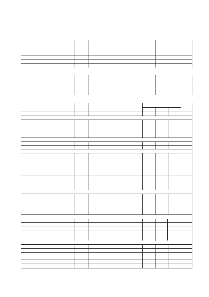
Specifications
Absolute Maximum Ratings
at Ta = 25°C
Allowable Operating Ranges
at Ta = 25°C
Electrical Characteristics
at Ta = 25°C, V
CC
= 5 V, V
S
= 15 V
Notes : 1.The torque ripple correction ratio is determined as follows from the Rf voltage waveform.
2.Parameters that are indicated as design target values in the conditions column are not tested.
Continued on next page.
No. 5975-2/8
LB1999M
Parameter
Symbol
V
CC
max
V
S
max
I
O
max
Pd max
Topr
Tstg
Conditions
Ratings
Unit
V
V
A
W
°C
°C
Maximum supply voltage
7
24
1.3
0.95
Maximum output current
Allowable power dissipation
Operating temperature
Storage temperature
Independent device
–20 to + 75
–55 to + 150
Parameter
Symbol
V
S
V
CC
V
HALL
V
GSENSE
Conditions
Ratings
Unit
V
V
mVo-p
V
Supply voltage
5 to 22
4.5 to 5.5
±30 to ±80
–0.20 to + 0.20
Hall input amplitude
GSENSE pin input range
Between the Hall inputs
With respect to the control system ground
Parameter
Symbol
Conditions
Ratings
Unit
min
typ
max
VCC supply current
[Outputs]
I
CC
RL =
∞
, V
CTL
= 0 V (Quiescent)
12
18
mA
V
O
sat1
I
O
= 500 mA, Rf = 0.5
, Sink + Source
V
CTL
= V
LIM
= 5 V
(With saturation prevention)
I
O
= 1.0 A, Rf = 0.5
, Sink + Source
V
CTL
= V
LIM
= 5 V
(With saturation prevention)
2.1
2.6
V
Output saturation voltage
V
O
sat2
2.6
3.5
V
Output leakage current
[FR]
FR pin input threshold voltage
FR pin input bias current
[Control]
CTLREF pin voltage
CTLREF pin input range
CTL pin input bias current
I
O
leak
1.0
mA
V
FSR
I
B
(FSR)
2.25
–5.0
2.50
2.75
V
μ
A
V
CREF
V
CREFIN
I
B
(CTL)
2.37
1.7
2.50
2.63
3.50
8.0
V
V
μ
A
With V
CTL
= 5 V and the CTLREF pin open
With Rf = 0.5
, V
LIM
= 5 V, I
O
≥
10 mA,
Hall input logic fixed (U, V, W = H, H, L)
With Rf = 0.5
, V
LIM
= 5 V
With Rf = 0.5
,
I
O
= 200 mA,
Hall input logic fixed (U, V, W = H, H, L)
With Rf = 0.5
,
V
CTL
= 200 mV,
Hall input logic fixed (U, V, W = H, H, L)
CTL pin control start voltage
V
CTL
(ST)
2.20
2.35
2.50
V
CTL pin control switching voltage
V
CTL
(ST2)
3.00
3.15
3.30
V
CTL pin control Gm1
Gm (CTL)
0.52
0.65
0.78
A/V
CTL pin control Gm2
Gm2 (CTL)
1.20
1.50
1.80
A/V
[Current Limiter]
LIM current limit offset voltage
Voff (LIM)
With Rf = 0.5
, V
CTL
= 5 V, I
O
≥
10 mA,
Hall input logic fixed (U, V, W = H, H, L)
With V
CTL
= 5 V and the V
CREF
pin open,
V
LIM
= 0 V
With Rf = 0.5
, V
CTL
= 5 V, V
LIM
= 2.06 V,
Hall input logic fixed (U, V, W = H, H, L)
140
200
260
mV
LIM pin input bias current
I
B
(LIM)
–2.5
μ
A
LIM pin current control level
I
LIM
830
900
970
mA
[Hall Amplifier]
Hall amplifier input offset voltage
Hall amplifier input bias current
Hall amplifier common-mode input voltage range
Voff (HALL)
I
B
(HALL)
V
CM
(HALL)
–6
+6
3.0
3.3
mV
μ
A
V
1.0
1.3
For the high and low peaks in the Rf waveform
when I
O
= 200 mA.
(Rf = 0.5
)
*
1
Torque ripple correction ratio
TRC
9
%
[FG Amplifier]
FG amplifier input offset voltage
FG amplifier input bias current
Voff (FG)
I
B
(FG)
–8
+8
mV
nA
–100
FG amplifier output saturation voltage
V
O
sat (FG)
Sink side, for the load provided by the internal
pull-up resistor
0.5
0.6
V
FG bias voltage
FG amplifier common-mode input voltage
V
FGBI
V
GM
(FG)
2.4
0.5
2.5
2.6
4.0
V
V
相關(guān)PDF資料 |
PDF描述 |
|---|---|
| LB1999M | Three-Phase Brushless Motor Driver for VCR Capstan Motors |
| LB251 | CYAN LAMP LED |
| LB301 | BLUE OVAL LAMP LED |
| LB340 | BLUE LAMP LED |
| LB3500 | 1/8 Prescaler for PLL Electronic Tuning |
相關(guān)代理商/技術(shù)參數(shù) |
參數(shù)描述 |
|---|---|
| LB1999M | 制造商:SANYO 制造商全稱:Sanyo Semicon Device 功能描述:Three-Phase Brushless Motor Driver for VCR Capstan Motors |
| LB1A-B1B | 制造商:IDEC Corporation 功能描述:LENS, ROUND, BLACK, PUSHBUTTON SWITCH 制造商:IDEC Corporation 功能描述:LENS, ROUND, BLACK, PUSHBUTTON SWITCH; For Use With:Non Illuminated Push Button Switches; Mounting Hole Dia:16mm; Lens Color:Black |
| LB1A-B1G | 制造商:IDEC Corporation 功能描述:LENS, ROUND, GREEN, PUSHBUTTON SWITCH 制造商:IDEC Corporation 功能描述:LENS, ROUND, GREEN, PUSHBUTTON SWITCH; For Use With:Non Illuminated Push Button Switches; Mounting Hole Dia:16mm; Lens Color:Green |
| LB1A-B1R | 制造商:IDEC Corporation 功能描述:LENS, ROUND, RED, PUSHBUTTON SWITCH 制造商:IDEC Corporation 功能描述:LENS, ROUND, RED, PUSHBUTTON SWITCH; For Use With:Non Illuminated Push Button Switches; Mounting Hole Dia:16mm; Lens Color:Red |
| LB1A-B1S | 制造商:IDEC Corporation 功能描述:LB Button/Lens kit Blue |
發(fā)布緊急采購,3分鐘左右您將得到回復(fù)。