- 您現(xiàn)在的位置:買賣IC網(wǎng) > PDF目錄358745 > LB1412M (Sanyo Electric Co.,Ltd.) Level Meter Driver for 12 LEDs(驅動12個LED的電平驅動器) PDF資料下載
參數(shù)資料
| 型號: | LB1412M |
| 廠商: | Sanyo Electric Co.,Ltd. |
| 英文描述: | Level Meter Driver for 12 LEDs(驅動12個LED的電平驅動器) |
| 中文描述: | 液位計12個LED(驅動12個驅動電源LED的電平驅動器) |
| 文件頁數(shù): | 2/5頁 |
| 文件大?。?/td> | 76K |
| 代理商: | LB1412M |

Electrical Characteristics
at Ta = 25°C, V
CC
= 12 V
Parameter
Symbol
I
BIN1
V
OH01
V
OL01
V
GA1
R
IN2
R
02
I
OL02
V
GA2
I
OL
Pin No.
8
9
9
Conditions
min
typ
–0.2
11.2
1.5
100
12
50
max
Unit
μA
V
V
dB
k
k
mA
times
mA
Input bias current
Amp (1)
Amp (1)
Amp (1)
Amp (1)
Amp (2)
Amp (2)
Amp (2)
Amp (2)
–3
0
Output saturation
voltage
Pins 9, 10 short
Pins 9, 10 short
10.5
1.0
30
11.6
2.0
Voltage gain
Input resistance
Load resistance
Output current
Voltage gain
Output current
10
11
11
8
16
65
12
2.2
20
35
3
6
1.8
13
2.0
17
17, 21
18, 19,
20, 22,
23
2 to 6
17, 21
2 to 6
D1, D5: 3 k
across V
Z
and I
LED
Output saturation voltage
V
sat
D2 to D4, D6 to D7: output
transistor on across V
Z
and I
LED
1.0
1.3
V
V
sat
I
off
I
off
D8 to D12: I
OLD1
to D5 = 30 mA
D1, D5: output transistor off
D8 to D12: output transistor off
D8: Voltage to turn on D8 by
applying DC voltage across V
Z
and
IN2
D8 light-up level: 0 dB
D8 light-up level: 0 dB
D8 light-up level: 0 dB
D8 light-up level: 0 dB
D8 light-up level: 0 dB
D8 light-up level: 0 dB
D8 light-up level: 0 dB
D8 light-up level: 0 dB
D8 light-up level: 0 dB
D8 light-up level: 0 dB
D8 light-up level: 0 dB
3 k
across V
Z
and I
LED
V
R
= 0 V, OSC pin open
OSC pin open
1 M
, 2.2 μF across V
CC
and V
Z
3 k
across V
Z
and I
LED
, all D
outputs off
1.5
2.0
30
30
V
μA
μA
Output leak current
0
0
Comparator level
D8
V
THD8
2
–0.625
–0.55
–0.465
V
D1
D2
D3
D4
D5
D6
D7
D9
D10
D11
D12
G
D1
G
D2
G
D3
G
D4
G
D5
G
D6
G
D7
G
D9
G
D10
G
D11
G
D12
V
Z
I
OLR
V
R
f
OSC
17
18
19
20
21
22
23
3
4
5
6
13
12
12
14
–23
–17
–12
–8
–6
–4
–1.5
0.5
–20
–15
–10
–7
–5
–3
–1
–17
–13
–8
–6
–4
–2
–0.5
1.5
dB
dB
dB
dB
dB
dB
dB
dB
dB
dB
dB
V
mA
V
s
1
3
5
8
2
4
7
4
6
9
Reference voltage
R pin flow-out current
R pin voltage
Oscillation frequency
5.6
–0.6
0.4
1.5
6.3
–0.3
0.7
6.8
–0.1
0.9
2.5
2
Current drain
I
CC
16
9
15
mA
A
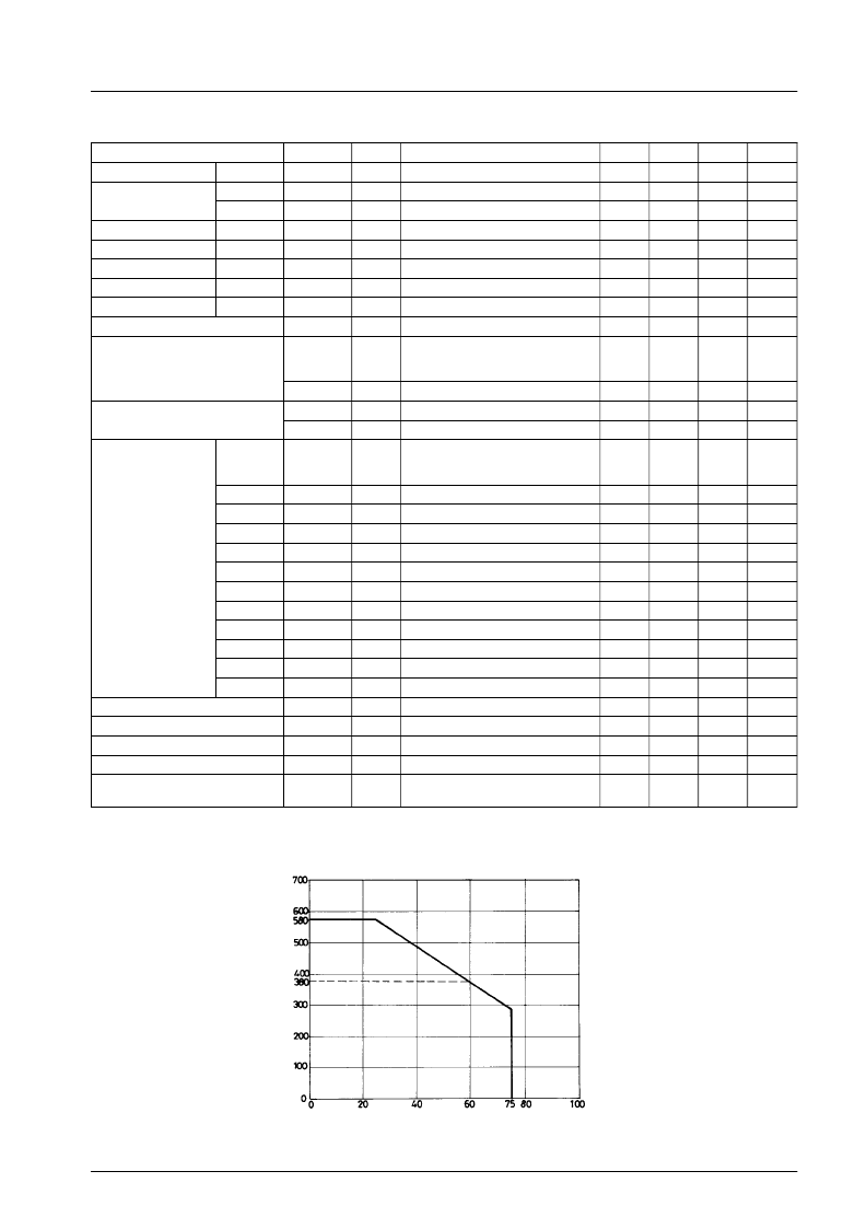
Pd max – Ta
Ambient temperature, Ta – °C
LB1412M
No.1593-2/5
相關PDF資料 |
PDF描述 |
|---|---|
| LB1412 | Level Meter Driver for 12 LEDs |
| LB1413N | 5-Dot Red/Green LED Level Meter(5點紅/綠色LED電平表) |
| LB1436 | Level Meter(電平表) |
| LB1450 | LED Tuning Indicator(LED調諧指示器) |
| LB1475 | 2-Wire Type Wired Remote Controller |
相關代理商/技術參數(shù) |
參數(shù)描述 |
|---|---|
| LB1413 | 制造商:未知廠家 制造商全稱:未知廠家 功能描述: |
| LB1413N | 制造商:SANYO 制造商全稱:Sanyo Semicon Device 功能描述:5-Dot Red/Green LED Level Meter |
| LB1415 | 制造商:SANYO 制造商全稱:Sanyo Semicon Device 功能描述:Level Meter |
| LB1416 | 制造商:Panasonic Industrial Company 功能描述:IC |
| LB1417 | 制造商:SANYO 制造商全稱:Sanyo Semicon Device 功能描述:AC/DC Voltage Level Meter |
發(fā)布緊急采購,3分鐘左右您將得到回復。