- 您現(xiàn)在的位置:買賣IC網(wǎng) > PDF目錄30719 > LA4663N 20 W, 2 CHANNEL, AUDIO AMPLIFIER, ZFM14 PDF資料下載
參數(shù)資料
| 型號: | LA4663N |
| 元件分類: | 音頻/視頻放大 |
| 英文描述: | 20 W, 2 CHANNEL, AUDIO AMPLIFIER, ZFM14 |
| 封裝: | SIP-14 |
| 文件頁數(shù): | 7/10頁 |
| 文件大小: | 144K |
| 代理商: | LA4663N |
LA4663N
No.5904-6/10
Usage Notes
1. Maximum ratings
If the device is operated in the vicinity of the maximum ratings, it is possible for small changes in the operating
conditions to result in the maximum ratings being exceeded. Since this can result in destruction of the device,
applications should be designed with adequate margins in the supply voltage and other parameters so that the maximum
ratings are never exceeded during device operation.
2. Protection circuits
While the LA4663N includes a full complement of built-in protection circuits, care is required in the usage. In
particular, be careful not to short any pairs of device pins together.
[Notes on the shorting (power, ground, and load shorting) protection circuit]
This protection circuit operates whenever a power short (a short between the output and VCC), a ground short (a short
between the output and ground), or a load short (shorting between the + and – outputs) is detected. Although there are
cases where the protection circuit may not operate if the supply voltage is under 9V, the thermal protection circuit will
protect the device in this range.
The protection circuit continues to operate during the interval that the abnormal short continues, and automatically
recovers when the error state is resolved. However, under certain usage conditions, there are situations where the
protection circuit may lock and remain locked even after the problem has been resolved. In these cases, the circuit can
be reset by switching to standby mode or turning off the power temporarily.
If the output is shorted to VCC with the IC in the standby state and furthermore, a VCC of 20V or higher applied, an
offset will be created between the + and – outputs. If a load is connected in this state, a current will flow in that load,
and the IC may be destroyed. Applications should assure that this does not occur.
In the following situations, the operation of the protection circuit may result in a sound switching phenomenon at high
output levels. This may be a problem, depending on the details of the end product circuit itself, and must be verified in
an actual system.
At low load resistances RL (high loads) and at high VCC voltages, and with both channels operating at IO peak levels
of over 2A per channel. (This phenomenon is more likely to occur the higher the chip temperature.)
For systems operating under the most sever conditions (high temperatures and high outputs), specific operating
conditions such that the above phenomenon does no occur are listed in the “Allowable operating supply voltage range
(VCC op)” item in the Operating Conditions section of the specifications. (Refer to the VCC op ranges for different RL
values.)
[Thermal protection circuit]
A thermal protection circuit is provided to prevent damage to or destruction of the IC itself when the IC generates
abnormally high temperatures. This means that gradual attenuation is applied to the output signals by the thermal
protection circuit if the IC junction temperature (Tj) rises above about 160°C due to insufficient heat sinking or other
problems.
3. Notes on printed circuit boards
When designing the printed circuit board pattern, keep the input lines separated from both the VCC lines and the output
lines. This is to prevent increased distortion and oscillation.
When high output levels are used, make power-ground lines as wide as possible and as short as possible to prevent the
PWR GND pins potential from increasing with respect to pre-ground. (From the standpoint of IC stability, ideally, the
ground pin potential should be the lowest potential in the system. This is to prevent trouble caused by several types of
induced parasitic devices due to increases in the GND pin potential due to the structure of the IC.)
4. Notes on heat sink mounting
Use a tightening torque of between 39 and 59Ncm.
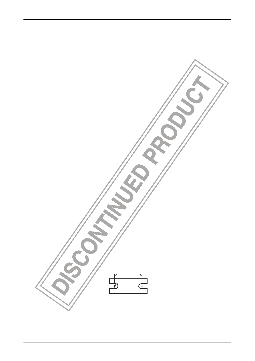
Make the spacing of the heat sink mounting screw holes the same as the spacing of the IC mounting screw holes. Also,
make the mounting screw hole spacing as short as possible within the range that still allows mounting, referring to the
external dimensions L and R.
R
L
For mounting screws, use screws that correspond to either the truss screws or binding screws stipulated by the JIS
(Japan Industrial Standards). Use washers to protect the IC case.
Do not allow any foreign matter, such as machining chips, to get between the IC (package internal) heat sink and the
external heat sink. Also, if grease is applied to the junction, apply the grease as evenly as possible.
5. Other notes
The LA4663N is a BTL power amplifier IC. When connecting this IC to test equipment, do not allow the test
equipment grounds for the input and output systems to be shared grounds.
相關(guān)PDF資料 |
PDF描述 |
|---|---|
| LA4663 | 20 W, 2 CHANNEL, AUDIO AMPLIFIER, PZFM14 |
| LA4700N | 12 W, 2 CHANNEL, AUDIO AMPLIFIER, PSFM18 |
| LA4705 | 18 W, 2 CHANNEL, AUDIO AMPLIFIER, PSFM18 |
| LA4708 | 30 W, 2 CHANNEL, AUDIO AMPLIFIER, SFM18 |
| LA47202P | 29 W, 4 CHANNEL, AUDIO AMPLIFIER, ZFM25 |
相關(guān)代理商/技術(shù)參數(shù) |
參數(shù)描述 |
|---|---|
| LA46B-DBKUG-7-PF | 制造商:LIGITEK 制造商全稱:LIGITEK electronics co., ltd. 功能描述:LED ARRAY |
| LA46B-EG-4-PF | 制造商:LIGITEK 制造商全稱:LIGITEK electronics co., ltd. 功能描述:LED ARRAY |
| LA46B-EG-9-PF | 制造商:LIGITEK 制造商全稱:LIGITEK electronics co., ltd. 功能描述:LED ARRAY |
| LA46B-EG-S2-PF | 制造商:LIGITEK 制造商全稱:LIGITEK electronics co., ltd. 功能描述:LED ARRAY |
| LA46B-EG-S9-PF | 制造商:LIGITEK 制造商全稱:LIGITEK electronics co., ltd. 功能描述:LED ARRAY |
發(fā)布緊急采購,3分鐘左右您將得到回復(fù)。