- 您現(xiàn)在的位置:買賣IC網(wǎng) > PDF目錄30717 > LA4277 5 W, 2 CHANNEL, AUDIO AMPLIFIER, SFM10 PDF資料下載
參數(shù)資料
| 型號(hào): | LA4277 |
| 元件分類: | 音頻/視頻放大 |
| 英文描述: | 5 W, 2 CHANNEL, AUDIO AMPLIFIER, SFM10 |
| 封裝: | SIP-10 |
| 文件頁數(shù): | 4/7頁 |
| 文件大小: | 129K |
| 代理商: | LA4277 |

LA4277
No.7095-4/7
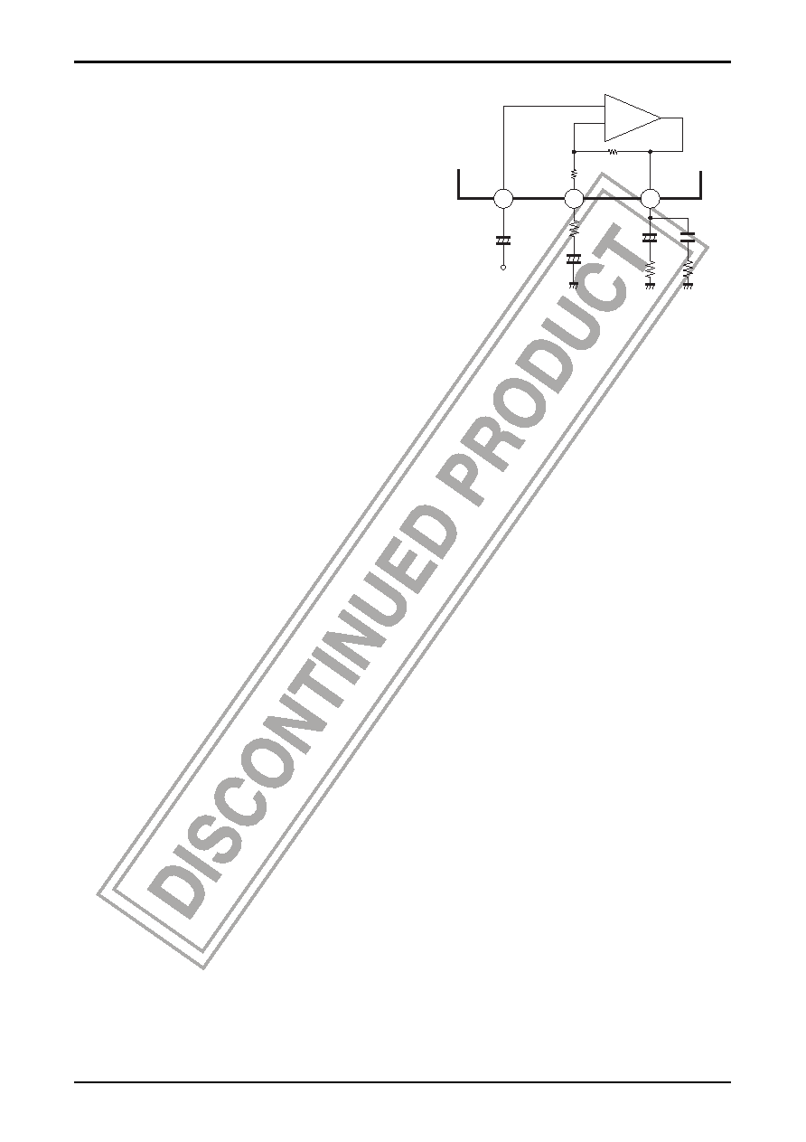
Voltage Gain
The voltage gain can be lowered by adding external resistors
R1/R5 in series to feedback capacitors C1/C5. When R1/R5 =
150
Ω, the voltage gain is 40dB. However, it is important to note
that because there is no phase compensation pin, decreasing the
voltage gain can extend the high frequency characteristics,
allowing oscillation to occur easily.
RNF
IN1(2)
NF1(2)
OUT1(2)
C7/C10
R2/R3
C6/C9
R1/R5
C2/C4
(5)
(6)
(7)
C1/C5
RL
Rf 20k
Ω
56
Ω
2
1
10
+
Notes on Using the IC
Maximum ratings
When this IC is used near its maximum ratings, it is possible that a slight fluctuation in the operating conditions could
cause the maximum ratings to be exceeded, damaging the IC. Therefore, allow for an adequate safety margin in regards
to supply voltage, etc., so that the IC is never used under conditions that exceed its maximum ratings.
Short circuit between pins
Applying power to the IC while a short circuit exists between two pins can cause damage or deterioration in the IC.
Therefore, after mounting the IC on a board, make sure that there are no solder bridges, etc., causing a short circuit
between any of the pins before applying power to the IC.
Using the IC in a radio
When using this IC in a radio, make sure that there is enough distance between the IC and the bar antenna.
Printed circuit pattern
When designing the printed circuit pattern, keep power, output, and ground lines thick and short, and determine the
placement of the pattern and the components in such a way as to prevent the generation of an I/O feedback loop.
In addition, power supply capacitor C8 and oscillation blocking capacitor C7 and C10 should be placed as close as
possible to the IC pins in order to prevent oscillation.
相關(guān)PDF資料 |
PDF描述 |
|---|---|
| LA4278 | 10 W, 2 CHANNEL, AUDIO AMPLIFIER, SFM10 |
| LA4280 | 11.5 W, 2 CHANNEL, AUDIO AMPLIFIER, PSIP14 |
| LA4282 | 11.5 W, 2 CHANNEL, AUDIO AMPLIFIER, PSFM12 |
| LA4285 | 3 W, 1 CHANNEL, AUDIO AMPLIFIER, PSFM10 |
| LA4287 | 6 W, 1 CHANNEL, AUDIO AMPLIFIER, SFM10 |
相關(guān)代理商/技術(shù)參數(shù) |
參數(shù)描述 |
|---|---|
| LA4277-E | 制造商:Sony Semiconductor Solutions Division 功能描述: |
| LA4278 | 制造商:SANYO 制造商全稱:Sanyo Semicon Device 功能描述:10 W 2-Channel Power Amplifier |
| LA4278-E | 制造商:Sony Semiconductor Solutions Division 功能描述: |
| LA4280 | 制造商:SANYO 制造商全稱:Sanyo Semicon Device 功能描述:2-Channel 10W AF Power Amp for Home Stereo, TV Use |
| LA4280-E | 制造商:Sony Semiconductor Solutions Division 功能描述: |
發(fā)布緊急采購,3分鐘左右您將得到回復(fù)。