- 您現(xiàn)在的位置:買賣IC網(wǎng) > PDF目錄30717 > LA4265 3.5 W, 1 CHANNEL, AUDIO AMPLIFIER, PSFM10 PDF資料下載
參數(shù)資料
| 型號: | LA4265 |
| 元件分類: | 音頻/視頻放大 |
| 英文描述: | 3.5 W, 1 CHANNEL, AUDIO AMPLIFIER, PSFM10 |
| 封裝: | SIP-10 |
| 文件頁數(shù): | 7/9頁 |
| 文件大?。?/td> | 136K |
| 代理商: | LA4265 |

LB8118M
No.5838-7/11
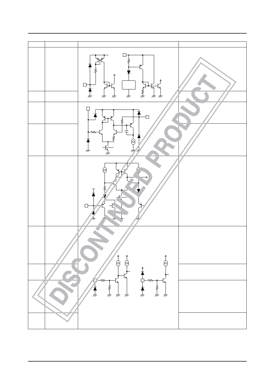
Continued from preceding page.
Pin No.
Symbol
Equivalent circuit
Function
20
VZ
Input pin for start-up circuit when an
external voltage input is applied. The
external voltage input is applied
through a resistor inserted in series.
The voltage is basically determined
1.2 V + 2VBE; this pin has a current
draining capacity up to 20 mA.
27
S/S
LB8118M start-up input. (Start
on a low-level input.)
23
VLD
Laser diode voltage detection pin. The
VLD voltage +0.5 V is VAPC.
24
VAPC
Voltage feedback input pin for the APC
step-up voltage circuit.
The step-up power supply voltage is
determined by comparing this input
voltage with VLD.
16
VOSET
H bridge power supply limiter voltage
pin for the VOUT2 side.
The voltage is limited at approximately
190% of the VOSET voltage. The setting
is made by a dividing resistor.
13
CHG-ON
Pin for selecting battery charging when
external voltage input is applied. This
pin is used to determine the drop
voltage for the external voltage input.
When low, the drop voltage set by
VEXT is selected; when high, the drop
voltage set by VEXT-CHG is selected.
28
MUTE
Input pin for simultaneously muting the
four-channel drivers. Mute when
turning the power on. (Low level: mute)
44
1ch/2ch
This pin is used to switch the H bridge
power supply between two-channel
simultaneous operation and one-
channel operation. (Two-channel
operation is selected when this pin is
low.)
34
SLMODE
Pin for switching the sled driver
between V-type control and step control.
(High: V-type control; low: step control)
Continued on next page.
S/S
100
kΩ
1.2V
VREF
VZ
1.3kΩ
A09987
A09988
50μA
VAPC
VLD
A09989
Voset
VCC
3.6kΩ
VCD
SLMODE
80kΩ
60kΩ
20μA20μA
VCD
VCC
MUTE
CHG-ON
80kΩ
60kΩ
20μA
VCC
A09990
To next block
Reference
voltage
startup circuit
External
power
input
Forced
startup
相關(guān)PDF資料 |
PDF描述 |
|---|---|
| LA4266 | 3 W, 1 CHANNEL, AUDIO AMPLIFIER, PSFM10 |
| LA4267 | 5 W, 1 CHANNEL, AUDIO AMPLIFIER, PSFM10 |
| LA4268 | 10 W, 1 CHANNEL, AUDIO AMPLIFIER, PSFM10 |
| LA4270 | 6 W, 2 CHANNEL, AUDIO AMPLIFIER, PSIP10 |
| LA4275 | 6 W, 1 CHANNEL, AUDIO AMPLIFIER, PSFM7 |
相關(guān)代理商/技術(shù)參數(shù) |
參數(shù)描述 |
|---|---|
| LA4266 | 制造商:SANYO 制造商全稱:Sanyo Semicon Device 功能描述:3 W Monaural Power Amplifier |
| LA4267 | 制造商:SANYO 制造商全稱:Sanyo Semicon Device 功能描述:5 W Monaural Power Amplifier |
| LA4268 | 制造商:SANYO 制造商全稱:Sanyo Semicon Device 功能描述:10 W Monaural Power Amplifier |
| LA4268-E | 制造商:Sony Semiconductor Solutions Division 功能描述: |
| LA4270 | 制造商:SANYO 制造商全稱:Sanyo Semicon Device 功能描述:2-CHANNEL AF POWER AMP FOR TAPE RECORDER RADIO |
發(fā)布緊急采購,3分鐘左右您將得到回復(fù)。