- 您現(xiàn)在的位置:買賣IC網(wǎng) > PDF目錄30715 > LA1862M FM, AUDIO DEMODULATOR, PDSO36 PDF資料下載
參數(shù)資料
| 型號: | LA1862M |
| 元件分類: | 接收器 |
| 英文描述: | FM, AUDIO DEMODULATOR, PDSO36 |
| 封裝: | MFP-36 |
| 文件頁數(shù): | 5/27頁 |
| 文件大?。?/td> | 810K |
| 代理商: | LA1862M |
第1頁第2頁第3頁第4頁當前第5頁第6頁第7頁第8頁第9頁第10頁第11頁第12頁第13頁第14頁第15頁第16頁第17頁第18頁第19頁第20頁第21頁第22頁第23頁第24頁第25頁第26頁第27頁

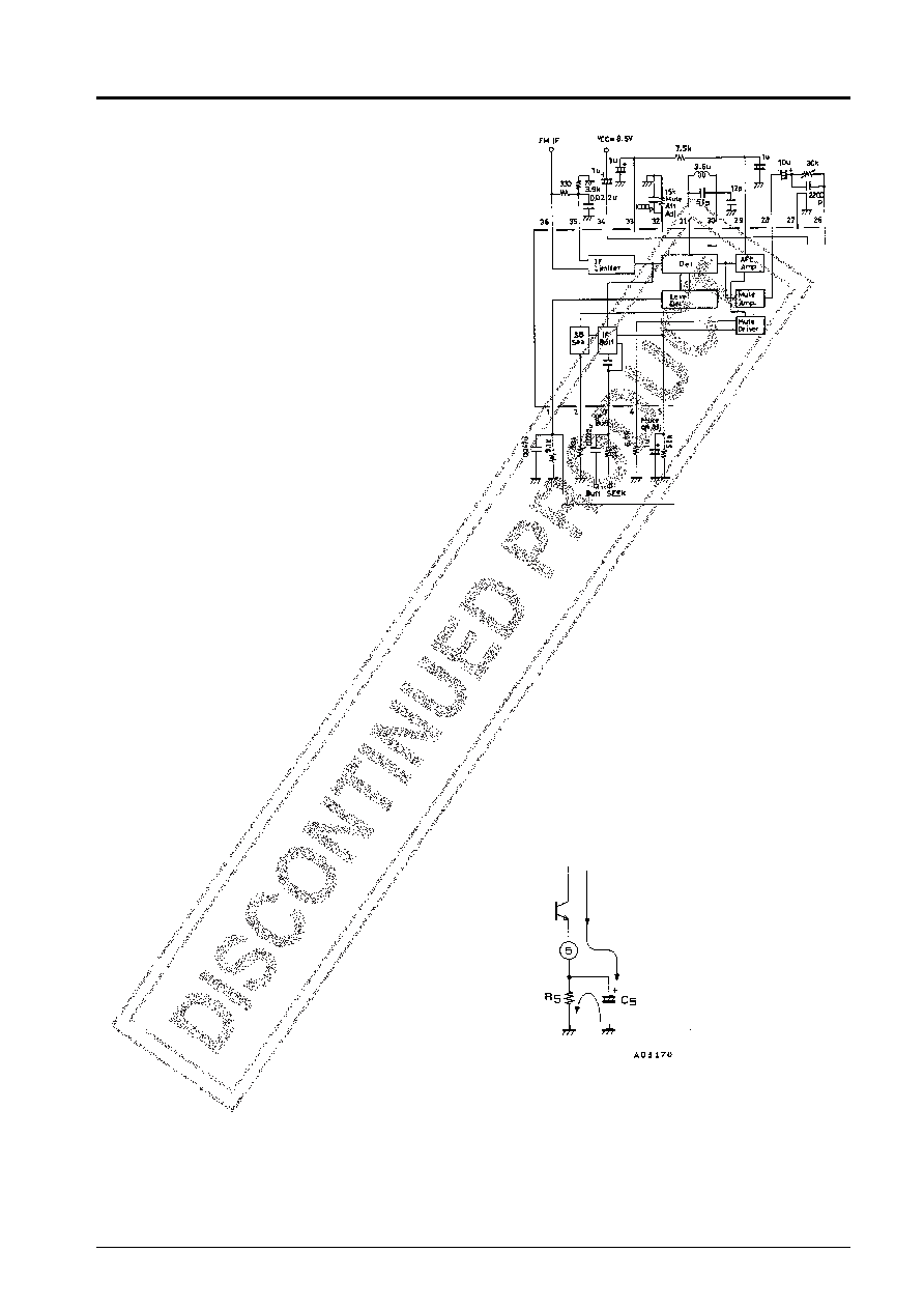
IF Block
Obtaining Stable Characteristics
1.
Pin 36 is the IF input; pin 35, the IF bypass. Connect a
330
Ω resistor between them for ceramic filter matching.
2.
Position the capacitor between thr IF bypass (pin 35) and
the ground pattern so as to maximize AM rejection.
3.
Provide separate ground pattern islands for the IF input
and detection circuits, as sharing the same island reduces
stability.
4.
Position the IF input and detector coil as far apart as
possible, as proximity reduces stability and introduces beat
noise in the output.
S-meter Output VSM
1.
Pin 1 is the field strength indicator (or ‘‘S-meter’’) output. Its current-driven circuit uses an external resistance to adjust the
slopes of the I/O characteristics curves.
2.
The S-meter output is internally connected to the soft muting and IF buffer blocks for use as a control signal for the soft
muting drive and IF count buffer.
3.
The point at which the input produces an S-meter output depends on the front end (FE) and interstage amplifier gains.
4.
Too large a front end gain produces floating S-meter output even when there is no input. Either use a smaller load resistance
on pin 1 or reduce the front end gain so that the output with no load does not exceed 0.5 V.
5.
The S-meter output circuit has a dynamic range of approximately 80 dB, but this is limited by the front end noise component
and broadband AGC circuit.
Soft Muting
1.
The soft muting circuit operates in response to the S-meter output voltage. The amount of muting is related to the pin 5
output voltage.
2.
There are two mechanisms for adjusting the soft muting
I/O characteristic curve:
a. Start point for muting: Resistance attached to pin 4
b. Attenuation for muting: Resistance attached to pin 32
*Note that the resistance attached to pin 1 also affects the
curve.
3.
The soft muting circuit automatically varies the amount of
muting in response to the IF input. In the absence of front
end broadband AGC effects, the time constant of the RC
circuit between pins 1 and 5 determines the response.
Band Muting
1.
Band muting uses the detector’s S-curve. The band-width depends on the resistance between pins 29 and 33. Select this value
to match the needs of the destination market.
2.
Keep in mind that changing the detector coil or tuning capacity Q changes the slope of the S-curve and hence the bandwidth.
3.
The attenuation muting depends on the resistance connected to pin 32.
4.
The muting transient response depends on the resistance between pins 29 and 33, the capacitance at pin 29, and the time
constant for the RC circuit at pin 5.
Unit (resistance:
Ω, capacitance: F)
(Muting drive output)
Charging
current
Time constant for charging
re
× C5 = τ
Time constant for discharging
R5 × C5 = τ
Discharging
current
LA1862M
No. 4092- 13/27
相關(guān)PDF資料 |
PDF描述 |
|---|---|
| LA1863M | 1-BAND, AUDIO TUNER, PQFP44 |
| LA1867NM | AM/FM, AUDIO DEMODULATOR, PQFP44 |
| LA1875M | AM/FM, AUDIO SINGLE CHIP RECEIVER, PDSO36 |
| LA1875M | AM/FM, AUDIO SINGLE CHIP RECEIVER, PDSO36 |
| LA1883M | AM/FM, AUDIO SINGLE CHIP RECEIVER, PQFP64 |
相關(guān)代理商/技術(shù)參數(shù) |
參數(shù)描述 |
|---|---|
| LA1867NM | 制造商:SANYO 制造商全稱:Sanyo Semicon Device 功能描述:Car Radio Single-Chip Tuner System |
| LA1867NM-MPB-E | 制造商:ON Semiconductor 功能描述: |
| LA186B-9SEF9UG-3-PF | 制造商:LIGITEK 制造商全稱:LIGITEK electronics co., ltd. 功能描述:LED ARRAY |
| LA186B-9SEF-PF | 制造商:LIGITEK 制造商全稱:LIGITEK electronics co., ltd. 功能描述:LED ARRAY |
| LA186B-DBK-2-PF | 制造商:LIGITEK 制造商全稱:LIGITEK electronics co., ltd. 功能描述:LED ARRAY |
發(fā)布緊急采購,3分鐘左右您將得到回復(fù)。