- 您現(xiàn)在的位置:買賣IC網(wǎng) > PDF目錄30714 > LA1776M 2-BAND, AUDIO TUNER, PQFP64 PDF資料下載
參數(shù)資料
| 型號: | LA1776M |
| 元件分類: | 調(diào)諧器 |
| 英文描述: | 2-BAND, AUDIO TUNER, PQFP64 |
| 封裝: | 14 X 14 MM, QFP-64 |
| 文件頁數(shù): | 24/41頁 |
| 文件大小: | 547K |
| 代理商: | LA1776M |
第1頁第2頁第3頁第4頁第5頁第6頁第7頁第8頁第9頁第10頁第11頁第12頁第13頁第14頁第15頁第16頁第17頁第18頁第19頁第20頁第21頁第22頁第23頁當(dāng)前第24頁第25頁第26頁第27頁第28頁第29頁第30頁第31頁第32頁第33頁第34頁第35頁第36頁第37頁第38頁第39頁第40頁第41頁

No.8085-30/41
LA1776M
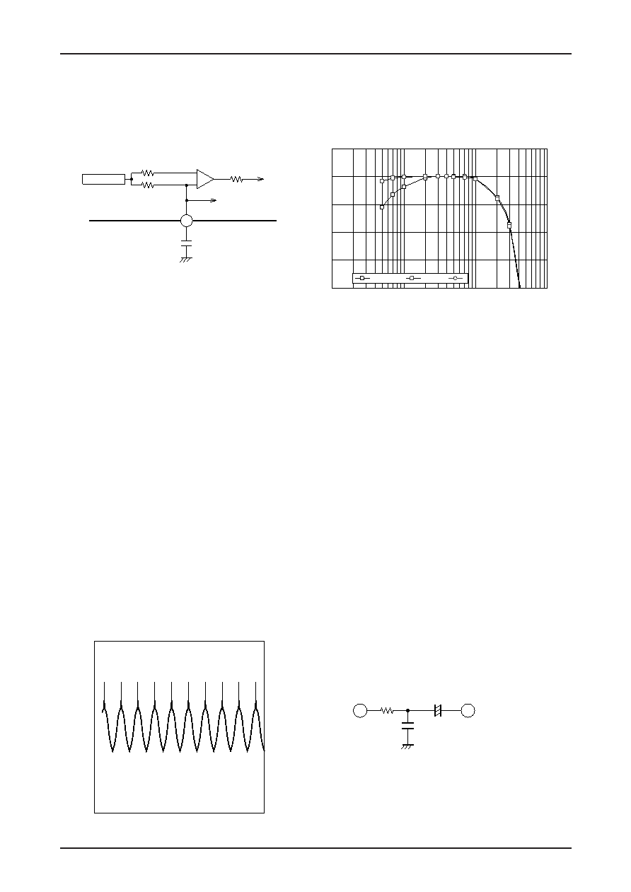
5-4. AM Low Region Cut Adjustment
The AM low frequency region frequency characteristics can be adjusted with capacitor C42, which is inserted
between pin 42 and ground. Since this capacitor is shared with the FM pilot detector, it is connected to ground.
To prevent incorrect operation of the pilot detector, C42 must have a value of 0.33 F or higher.
6. Noise Canceller Block
6-1. The noise canceller input (pin 30) has an input impedance of about 50 k
. The low band frequency
characteristics require care when determining the value for the coupling capacitor. Note that fC will be about 3
Hz in an application that uses a 1 F capacitor.
6-2. The noise detection sensitivity and the noise AGC are set with pins 8 and 9. Good settings can be acquired by
first setting the medium field strength (corresponding to an antenna input of about 50 dB) sensitivity with the
noise sensitivity setting pin (pin 8) and then setting the weak field (20 to 30 dB) with the AGC adjustment pin
(pin 9). Note that if the noise detection sensitivity is increased, the effect of the AGC will be improved, but that
inversely the weak field sensitivity will be decreased.
The problem of incorrect operation of the noise canceller for 10 kHz overmodulation occurs when an
overmodulated signal is input and the noise canceller responds to that signal even though it should not. The
cause of this is the IF detector output taking on the sort of waveform shown in the figure due to the band of the
IF ceramic filter as shown below. (150 kHz
× 1, 180 kHz (r) 2, f = 10 kHz, 180 kHz deviation) The noise
canceller responds to the whisker components generated by this overmodulation, resulting in distortion of the
audio output. (The whisker components due to the overmodulation are generated by the band of the ceramic
filter in the tuner.) This can be prevented as follows. The incorrect operation due to the overmodulation can be
eliminated by removing the whisker components due to the overmodulation as described above with the low-
pass filter consisting of a 1 k
resistor and 220 pF capacitor as shown in the figure. Note, however, that the FM
separation characteristics in the high band and the AM frequency characteristics will change.
AM detector
42
C42
1 k
10 k
1 k
To 31PIN
Pilot det
+
–
Detector Output – f [dB]
–20
–15
–10
–5
0
5
0.01
0.1
1
10
Modulation frequency [kHz]
O
u
tp
u
t
[d
B
]
C42 = 0.47u
C42 = 1u
H1 W1
2.5OU
–2.5OU
–19.00
s
981.00
s
IF audio output
f = 10 kHz, 180 kHz dev
31
30
IF output
Noise canceller input
1 k
1
F
2200 pF
+
–
相關(guān)PDF資料 |
PDF描述 |
|---|---|
| LA1776M | 2-BAND, AUDIO TUNER, PQFP64 |
| LA1780M | 2-BAND, AUDIO TUNER, PQFP64 |
| LA1781M | AM/FM, AUDIO SINGLE CHIP RECEIVER, PQFP64 |
| LA1784M | AM/FM, AUDIO SINGLE CHIP RECEIVER, PQFP64 |
| LA1787NM | AM/FM, AUDIO SINGLE CHIP RECEIVER, PQFP64 |
相關(guān)代理商/技術(shù)參數(shù) |
參數(shù)描述 |
|---|---|
| LA1776M_09 | 制造商:SANYO 制造商全稱:Sanyo Semicon Device 功能描述:Single-Chip Tuner IC for Car Radios |
| LA1776M-MPB-E | 功能描述:調(diào)諧器 RoHS:否 制造商:NXP Semiconductors 功能: 噪聲系數(shù): 工作電源電壓: 最小工作溫度: 最大工作溫度: |
| LA177B/HG-2 | 制造商:LIGITEK 制造商全稱:LIGITEK electronics co., ltd. 功能描述:LED ARRAY |
| LA177B-1-SRG | 制造商:LIGITEK 制造商全稱:LIGITEK electronics co., ltd. 功能描述:LED ARRAY |
| LA177B-HG-2 | 制造商:LIGITEK 制造商全稱:LIGITEK electronics co., ltd. 功能描述:LED ARRAY |
發(fā)布緊急采購,3分鐘左右您將得到回復(fù)。