- 您現(xiàn)在的位置:買(mǎi)賣(mài)IC網(wǎng) > PDF目錄367494 > L8567-44PLCC Telecommunication IC PDF資料下載
參數(shù)資料
| 型號(hào): | L8567-44PLCC |
| 英文描述: | Telecommunication IC |
| 中文描述: | 通信集成電路 |
| 文件頁(yè)數(shù): | 11/42頁(yè) |
| 文件大小: | 701K |
| 代理商: | L8567-44PLCC |
第1頁(yè)第2頁(yè)第3頁(yè)第4頁(yè)第5頁(yè)第6頁(yè)第7頁(yè)第8頁(yè)第9頁(yè)第10頁(yè)當(dāng)前第11頁(yè)第12頁(yè)第13頁(yè)第14頁(yè)第15頁(yè)第16頁(yè)第17頁(yè)第18頁(yè)第19頁(yè)第20頁(yè)第21頁(yè)第22頁(yè)第23頁(yè)第24頁(yè)第25頁(yè)第26頁(yè)第27頁(yè)第28頁(yè)第29頁(yè)第30頁(yè)第31頁(yè)第32頁(yè)第33頁(yè)第34頁(yè)第35頁(yè)第36頁(yè)第37頁(yè)第38頁(yè)第39頁(yè)第40頁(yè)第41頁(yè)第42頁(yè)

Lucent Technologies Inc.
11
Data Sheet
August 1999
People’s Republic of China Applications
L8567 SLIC for
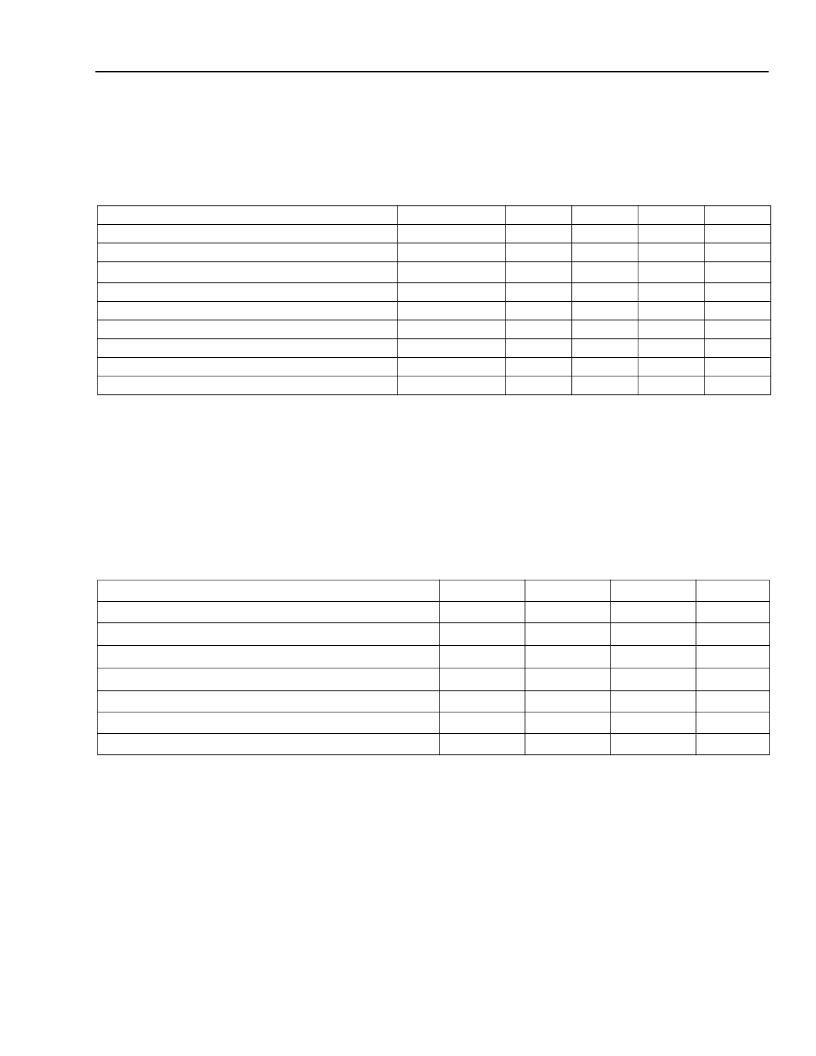
Absolute Maximum Ratings
(T
A
= 25
°
C)
Stresses in excess of the absolute maximum ratings can cause permanent damage to the device. These are abso-
lute stress ratings only. Functional operation of the device is not implied at these or any other conditions in excess
of those given in the operational sections of the data sheet. Exposure to absolute maximum ratings for extended
periods can adversely affect device reliability.
* Use of an auxiliary battery, V
BAT2
, whose magnitude is equal to the primary battery V
BAT1
but does not exceed the absolute maximum rating,
will not damage the chip. However, in a 32-pin PLCC, it will drive the L8567 into thermal shutdown under short-loop conditions. Use a power
resistor to node PWR.
Note: The IC can be damaged unless all ground connections are applied before, and removed after, all other connections. Furthermore, when
powering the device, the user must guarantee that no external potential creates a voltage on any pin of the device that exceeds the
device ratings. Some of the known examples of conditions that cause such potentials during powerup are 1) an inductor connected to tip
and ring can force an overvoltage on V
BAT
through the protection devices if the V
BAT
connection chatters, and 2) inductance in the V
BAT
lead could resonate with the V
BAT
filter capacitor to cause a destructive overvoltage.
Recommended Operating Conditions
Parameter
Symbol
V
CC
V
DD
V
BAT1,
V
BAT2
—
—
T
J
T
stg
R
H
—
Min
—
—
—
–0.5
–7.0
—
–40
5
—
Typ
—
—
—
—
—
—
—
—
—
Max
7.0
7.0
–70
7.0
7.0
165
125
95
±
3
Unit
V
V
V
V
V
°
C
°
C
%
V
+5 V Power Supply
+5 V Digital Supply
Battery (talking) Supplies
*
Logic Input Voltage
Analog Input Voltage
Maximum Junction Temperature
Storage Temperature Range
Relative Humidity Range
Ground Potential Difference (BGND to AGND)
Parameter
Min
–40
4.75
Typ
—
5.0
Max
85
5.25
Unit
°
C
V
Ambient Temperature
V
CC
Supply Voltage
V
DD
Supply Voltage
4.75
5.0
5.25
V
V
BAT1
Supply Voltage
V
BAT2
Auxiliary Battery Supply Voltage
dc Loop Current-limit Programming Range
On- and Off-hook 2-wire Signal Level
–65
–35
15
—
–48
–24
40
3.17
–35
–15
45
—
V
V
mA
dBm
相關(guān)PDF資料 |
PDF描述 |
|---|---|
| L8574D | CAP 15PF 50V 5% C0G SMD-0402 TR-7-PA SN100 |
| L8575 | Dual-Resistive,Low-Cost Subscriber Line Interface Circuit(SLIC) |
| L8576B | Dual Ringing SLIC |
| L8712(FECONLY) | IC TUBE FOR TO-220 508MM |
| L88R05_SERIES | |
相關(guān)代理商/技術(shù)參數(shù) |
參數(shù)描述 |
|---|---|
| L8574D | 制造商:AGERE 制造商全稱(chēng):AGERE 功能描述:L8574D Resistive Subscriber Line Interface Circuit(SLIC), Ring Relay,and Protector(SRP)for Long Loop and TR-57 Applications |
| L8575 | 制造商:Leviton Manufacturing Co 功能描述: |
| L8576B | 制造商:AGERE 制造商全稱(chēng):AGERE 功能描述:Dual Ringing SLIC |
| L8576BP | 制造商:Alcatel-Lucent 功能描述: 制造商:LUCENT 功能描述: |
| L85J250E | 制造商:Ohmite Mfg Co 功能描述: |
發(fā)布緊急采購(gòu),3分鐘左右您將得到回復(fù)。