- 您現(xiàn)在的位置:買賣IC網(wǎng) > PDF目錄383237 > L6615D (意法半導(dǎo)體) HIGH/LOW SIDE LOAD SHARE CONTROLLER PDF資料下載
參數(shù)資料
| 型號(hào): | L6615D |
| 廠商: | 意法半導(dǎo)體 |
| 英文描述: | HIGH/LOW SIDE LOAD SHARE CONTROLLER |
| 中文描述: | 高/低側(cè)負(fù)載共享控制器 |
| 文件頁數(shù): | 9/20頁 |
| 文件大小: | 392K |
| 代理商: | L6615D |
9/20
L6615
2
A sense resistor is typically used to generate the voltage drop, proportional to the load current, measured
by the CSA (Current Sense Amplifier), whose input pins (pins #2 and #3) are connected across of R
SENSE
through two identical resistors (RG1 and RG2).
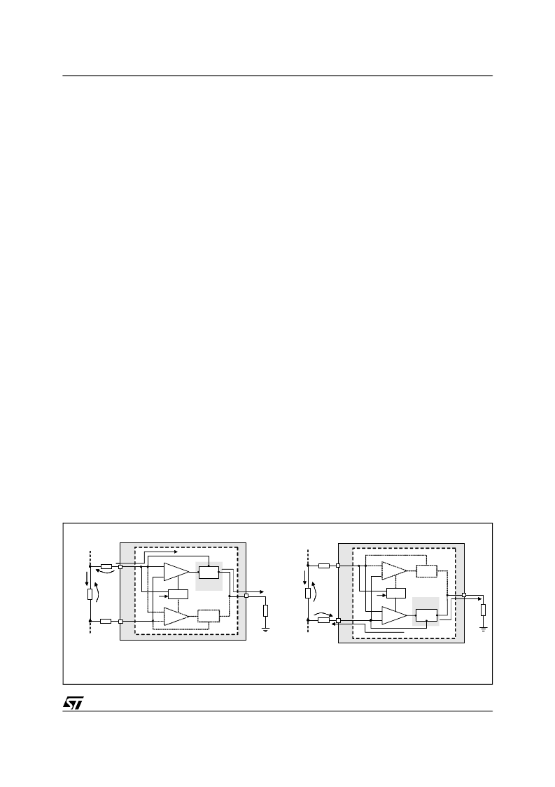
The CSA consists of 2 sections (see fig. 10), one responsible for the high side sensing, the other for low
side sensing. An internal comparator activates the relevant section in accordance with the voltage present
at CS+ pin: if this voltage is higher than 1.6V (typ), then the high side sensing section will be activated
(fig10.a) otherwise the low side sensing one will (fig 10.b). For the sake of simplicity we will consider R
G1
=
R
G2
= R
G
.
As the voltage drop I
OUT
*R
SENSE
is present at the input of the Sense Amplifier section, its output forces
the controlled current mirror to:
– sink current from the CS+ pin in case of high side sensing (neglecting input bias current, no current flows
through CS- pin);
– source current from the CS- pin in case of low side sensing (neglecting input bias current, no current
flows through CS- pin).
The local feedback imposes the same voltage at the current sense input pins, so under closed loop con-
dition V
SENSE
=VR
G
.
The current
CURRENT SENSE SECTION
(IC
S+
in case of high side, I
CS-
in case of low side) is then internally mirrored and sent to the CGA pin caus-
ing a drop across the R
CGA
external resistor: two internal buffers transfer V
CGA
signal on the share pin so:
Only the L6615 V
CC
limits the upper voltage at the CGA and SH pin, independently of the voltage present
at the current sense pins.
In noisy applications, two capacitors of small value (e.g. 1nF) connected between current sense pins and
ground could be useful to clean the signal at the input of the current sense amplifier.
For low voltage buses application, see paragraph 7.
Figure 10. Current sense section
I
CS
I
R
R
G
--------------------------------------
=
V
SH
V
R
G
--------------
R
CGA
=
COMPARE
CS-
CS+
+
CGA
PS+
LOAD(+)
I
OUT
R
SENSE
R
G
R
G
V
SENSE
I
CGA
I
CS+
V
RG
HSA
+
-
-
R
CGA
L6615
1.6V
MIRROR
1:1
SINK
CSA
LOAD(-) / GND
PS-
COMPARE
CS-
CS+
+
CGA
I
OUT
R
SENSE
R
G
R
G
V
SENSE
R
CGA
V
RG
HSA
+
-
-
L6615
1.6V
MIRROR
SOURCE
CSA
1:1
I
CS-
LSA
CONTROLLED
CURRENT
LSA
I
CGA
CONTROLLED
CURRENT
a) high side sensing
b) low side sensing
相關(guān)PDF資料 |
PDF描述 |
|---|---|
| L6615DTR | HIGH/LOW SIDE LOAD SHARE CONTROLLER |
| L6615N | HIGH/LOW SIDE LOAD SHARE CONTROLLER |
| L6660 | MILLI-ACTUATOR DRIVER |
| L6668 | SMART PRIMARY CONTROLLER |
| L6668TR | SMART PRIMARY CONTROLLER |
相關(guān)代理商/技術(shù)參數(shù) |
參數(shù)描述 |
|---|---|
| L6615D013TR | 功能描述:DC/DC 開關(guān)控制器 H/L Load Share Cont RoHS:否 制造商:Texas Instruments 輸入電壓:6 V to 100 V 開關(guān)頻率: 輸出電壓:1.215 V to 80 V 輸出電流:3.5 A 輸出端數(shù)量:1 最大工作溫度:+ 125 C 安裝風(fēng)格: 封裝 / 箱體:CPAK |
| L6615DTR | 制造商:STMICROELECTRONICS 制造商全稱:STMicroelectronics 功能描述:HIGH/LOW SIDE LOAD SHARE CONTROLLER |
| L6615N | 功能描述:DC/DC 開關(guān)控制器 H/L Load Share Cont RoHS:否 制造商:Texas Instruments 輸入電壓:6 V to 100 V 開關(guān)頻率: 輸出電壓:1.215 V to 80 V 輸出電流:3.5 A 輸出端數(shù)量:1 最大工作溫度:+ 125 C 安裝風(fēng)格: 封裝 / 箱體:CPAK |
| L6622-01 | 制造商:HAMAMATSU 制造商全稱:Hamamatsu Corporation 功能描述:130 KV MICROFOCUS X-RAY SOURCE |
| L-663 | 制造商:RHOMBUS-IND 制造商全稱:Rhombus Industries Inc. 功能描述:CURRENT SENSE INDUCTOR |
發(fā)布緊急采購,3分鐘左右您將得到回復(fù)。