- 您現(xiàn)在的位置:買賣IC網(wǎng) > PDF目錄383237 > L6450 (意法半導(dǎo)體) 28 Channel Ink Jet Driver(28通道噴墨驅(qū)動器) PDF資料下載
參數(shù)資料
| 型號: | L6450 |
| 廠商: | 意法半導(dǎo)體 |
| 英文描述: | 28 Channel Ink Jet Driver(28通道噴墨驅(qū)動器) |
| 中文描述: | 28頻道噴墨打印驅(qū)動程序(28通道噴墨驅(qū)動器) |
| 文件頁數(shù): | 4/9頁 |
| 文件大小: | 189K |
| 代理商: | L6450 |
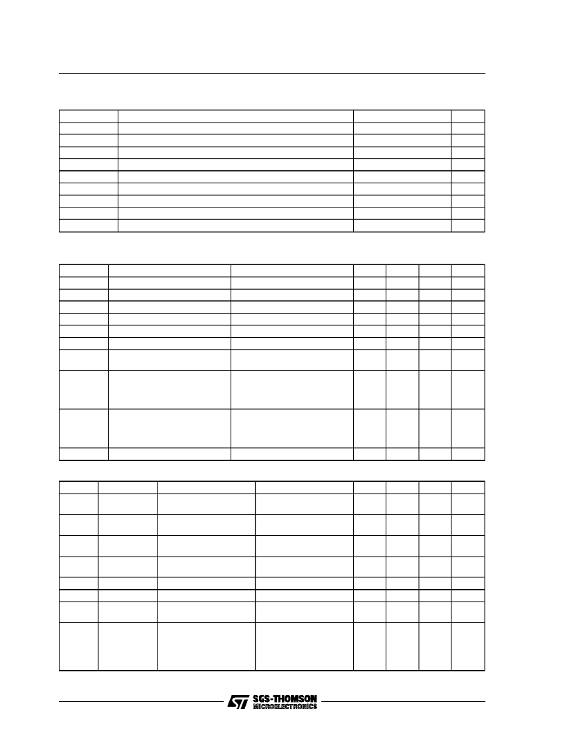
D.C. ELECTRICAL CHARACTERISTICS
atT
amb
= 25
°
C, V
DD
=5V,V
clamp
=18V(unlessotherwisespecified).
Symbol
V
DD
V
CLAMP
V
IL
V
IH
I
LL
I
LH
I
DD
Parameter
Test Condition
Min.
4.75
9
Typ.
5
Max.
5.25
38
1.2
Unit
V
V
V
V
μ
A
μ
A
mA
Logic Supply Voltage
Clamping Voltage
Low Level Input Voltage
High Level Input Current
Low Level Input Current
High Level Input Current
Logic Supply Current
V
DD
-1.2
V
IN
= V
IL
V
IN
= V
IH
(Indipendent from the output
conditions)
Tj 25
°
C D.C. 0.4A
Tj 25
°
C D.C. 0.5A
Tj 90
°
C D.C. 0.4A
Tj 90
°
C D.C. 0.5A
Tj = 25
°
C to 90
°
C D.C.:0.4A
Tj = 25
°
C to 90
°
C D.C.:0.5A
-200
10
5
V
OUT
Output Saturation Voltage
0.9
1.1
1.4
1.7
V
V
V
V
V
V
V
CE
Output saturation absolute
voltage variationaround the
typ. valuesfor extended
temperature ranges
±
0.2
±
0.25
R
DS
ON
2.2
ABSOLUTE MAXIMUMRATINGS
Symbol
V
OUT
V
CLAMP
I
OUT
I
PEAK
T
J
V
DD
V
IN
T
amb
T
stg
Parameter
Value
40
40
0.8
2
150
7
Unit
V
V
A
A
°
C
V
V
°
C
°
C
Output Voltage
Output Clamping Voltage
Output Continuous Current
Output Peak Current (with duty cycle = 10% T
ON
= 4
μ
s)
Junction Temperature
Logic Supply Voltage
Input Voltage Range
Operating Temperature Range
Storage Temperature Range
-0.3V to V
S
+0.3
0 to 70
-55 to 150
A.C. ELECTRICAL CHARACTERISTICS
at T
amb
= 25
°
C, V
DD
= 5V.
Symbol
T
S
Signal Name
INA, INB, INC,
IND Vs COMn
INA, INB, INC,
IND Vs COMn
COM1,2,3,4
V
S
OUT 0 toN
COM1,2,3,4
V
S
OUT 0 toN
Parameter
Test Condition
Min.
30
Typ.
Max.
Unit
ns
SET - UP Time
T
H
HOLD Time
0
ns
T
on
TURN - ON Time
I
OUT
= 0.5A, R
L
= 39
T
j
= 25 to 90
°
C
I
OUT
= 0.5A, R
L
= 39
T
j
= 25 to 90
°
C
150
ns
T
off
TURN - OFF Time
150
ns
t
r
t
f
Rise Time
Fall Time
Output Pulse Width
100
100
T
win
ns
ns
ns
T
wout
T
win
= 3.5
μ
s R
L
= 40
I
OUT
= 0.5A
R
L
= 39
V
CLAMP
= 18V
- 20
+ 80
P
D
Maximum allowable
variation of the output
power transmitted by
eachdriver to the
resistive load
±
4
%
L6450
4/9
相關(guān)PDF資料 |
PDF描述 |
|---|---|
| L6451 | 28 Channel Ink Jet Driver(28通道噴墨驅(qū)動器) |
| L6515 | DUAL DC-MOTOR POSITIONING SYSTEM |
| L6560 | POWER FACTOR CORRECTOR |
| L6560A | POWER FACTOR CORRECTOR |
| L6560AD | POWER FACTOR CORRECTOR |
相關(guān)代理商/技術(shù)參數(shù) |
參數(shù)描述 |
|---|---|
| L64500AGM | 制造商:未知廠家 制造商全稱:未知廠家 功能描述:16-Bit Microprocessor |
| L64500AGMB | 制造商:未知廠家 制造商全稱:未知廠家 功能描述:16-Bit Microprocessor |
| L64500AGMC | 制造商:未知廠家 制造商全稱:未知廠家 功能描述:MICROPROCESSOR|16-BIT|CMOS|PGA|144PIN|CERAMIC |
| L64500BGM | 制造商:未知廠家 制造商全稱:未知廠家 功能描述:16-Bit Microprocessor |
| L64500BGMB | 制造商:未知廠家 制造商全稱:未知廠家 功能描述:MICROPROCESSOR|16-BIT|CMOS|PGA|144PIN|CERAMIC |
發(fā)布緊急采購,3分鐘左右您將得到回復(fù)。