- 您現(xiàn)在的位置:買賣IC網(wǎng) > PDF目錄383231 > L482D1 (意法半導體) CAP 10UF 10V +80-20% Y5V SMD-1206 TR-7-PL SN100 PDF資料下載
參數(shù)資料
| 型號: | L482D1 |
| 廠商: | 意法半導體 |
| 英文描述: | CAP 10UF 10V +80-20% Y5V SMD-1206 TR-7-PL SN100 |
| 中文描述: | HALL.EFFECT皮卡點火控制器 |
| 文件頁數(shù): | 7/11頁 |
| 文件大小: | 169K |
| 代理商: | L482D1 |
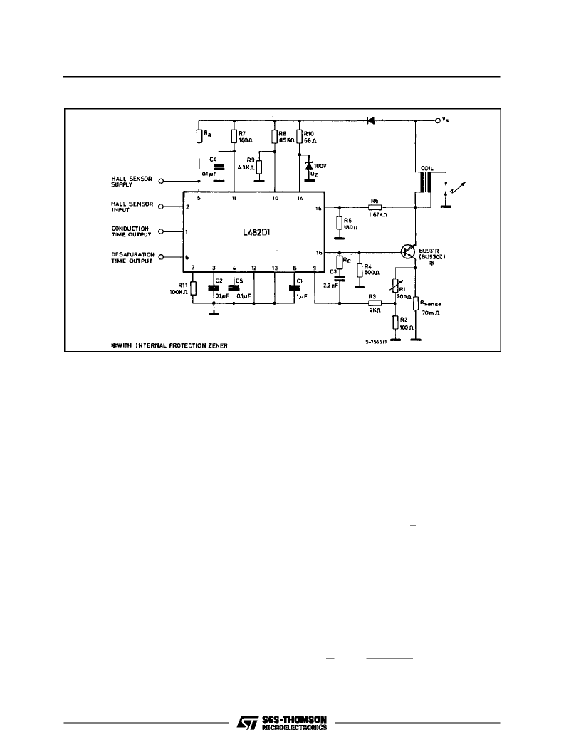
Figure 4 :
Application Circuit (SO–16).
CIRCUIT OPERATION
TheL482controltheconductiontime(dwell)andthe
peakvalueof theprimary currentin thecoiloverthe
full rangeof operatingconditions.
The coil current is limited to a predeterminedlevel
by meansof a negativefeedbackcircuit including a
current sensing resistor, a comparator, the driver
stageand the power switch.
The dwellcontrolcircuit maintainsthe outputstage
in itsactiveregionduringcurrentlimitation. Thetime
the outputstageis in theactiveregion(desaturation
time) is sufficient to compensatefor possiblevaria-
tions in thenergy storeddue to the accelerationof
the motor ; moreover thistime is limited to avoidex-
cessivepower dissipation.
CONTROL OF THE DWELL ANGLE (fig. 1 and 4)
The dwell angle control circuit calculates the con-
ductiontime Dfor the outputtransistorin relation to
the speedof rotation, to the supply voltage and to
the characteristic of thecoil.
On the negativeedgeof the Hall-effect input signal
the capacitorC
2
beginsdischargingwith a constant
currentI
3D
. When the set peakvalue of thecoil cur-
rent is reached, this capacitor charges with a con-
stant current I
3C
= 13.3 x I
3D
and the coil currentis
kept constantby desaturatingthe driver stage and
the externaldarlington.
The capacitor C
5
starts charging on the positive
edge of the Hall-effect input signal with a constant
currentI
4C
.
Thedwellangle,andconsequentlythestartingpoint
of thecoilcurrentproduction,isdecidedbythecom-
parisonbetweenV
C2
andV
C5
. Apositivehysteresis
is added to thedwell comparatorto avoidspurious
effectsand C
5
is rapidlydischargedon thenegative
edgeof Hall-effectsinput signal.
In this way the average voltageon C
2
increases if
the motorspeed decreases and viceversain order
to maintainconstanttheratiotdat anymotorspeed.
T
td is kept constant (and not d = cost) to control the
power dissipation and to have sufficient time to
avoidlow energy sparksduring acceleration.
The chargingtime D – td dependson the coil and
the voltagesupply.
DESATURATION TIMES IN STATIC CONDI-
TIONS.Instaticconditions,if C
2
=C
5
asrecommen-
dedand if the valuesof the applicationcircuit of fig.
3, 4are used.
td
1
=
T
1 + I
3C
/I
3D
L482
7/11
相關(guān)PDF資料 |
PDF描述 |
|---|---|
| L484 | MAGNETIC PICKUP IGNITION CONTROLLER |
| L484D1 | MAGNETIC PICKUP IGNITION CONTROLLER |
| L4902A | DUAL 5V REGULATOR WITH RESET AND DISABLE |
| L4903 | DUAL 5V REGULATOR WITH RESET AND DISABLE FUNCTIONS |
| L4904A | DUAL 5V REGULATOR WITH RESET |
相關(guān)代理商/技術(shù)參數(shù) |
參數(shù)描述 |
|---|---|
| L482D1013TR | 功能描述:馬達/運動/點火控制器和驅(qū)動器 Hall Effect Control RoHS:否 制造商:STMicroelectronics 產(chǎn)品:Stepper Motor Controllers / Drivers 類型:2 Phase Stepper Motor Driver 工作電源電壓:8 V to 45 V 電源電流:0.5 mA 工作溫度:- 25 C to + 125 C 安裝風格:SMD/SMT 封裝 / 箱體:HTSSOP-28 封裝:Tube |
| L483 | 制造商:未知廠家 制造商全稱:未知廠家 功能描述:THYRISTOR MODULE|SCR DOUBLER|280V V(RRM)|22A I(T) |
| L-483 | 制造商:KINGBRIGHT 制造商全稱:Kingbright Corporation 功能描述:T-1 (3mm) CYLINDRICAL LED LAMPS |
| L-483E | 制造商:KINGBRIGHT 制造商全稱:Kingbright Corporation 功能描述:T-1 (3mm) CYLINDRICAL LED LAMPS |
| L-483ED | 制造商:未知廠家 制造商全稱:未知廠家 功能描述:1.0x5.0x10.0mm RECTANGULAR LED LAMP |
發(fā)布緊急采購,3分鐘左右您將得到回復。