- 您現(xiàn)在的位置:買賣IC網(wǎng) > PDF目錄373162 > KM718FV4022 (SAMSUNG SEMICONDUCTOR CO. LTD.) 256Kx18 Synchronous SRAM(256Kx18位同步靜態(tài) RAM) PDF資料下載
參數(shù)資料
| 型號(hào): | KM718FV4022 |
| 廠商: | SAMSUNG SEMICONDUCTOR CO. LTD. |
| 英文描述: | 256Kx18 Synchronous SRAM(256Kx18位同步靜態(tài) RAM) |
| 中文描述: | 256Kx18同步SRAM(256Kx18位同步靜態(tài)內(nèi)存) |
| 文件頁數(shù): | 4/12頁 |
| 文件大?。?/td> | 267K |
| 代理商: | KM718FV4022 |

PRELIMINARY
Rev 0.2
Jan. 1998
KM718FV4022
128Kx36 & 256Kx18 SRAM
- 4 -
KM736FV4022
FUNCTION DESCRIPTION
The KM736FV4022 and KM718FV4022 are 4,718,592 bit Synchronous SRAM. It is organized as 131,072 words of 36 bits(or
262,144 words of 18 bits) and is implemented in SAMSUNG
′
s advanced CMOS technology.
Single differential PECL level K clocks are used to initiate the read/write operation and all internal operations are self-timed. At the
rising edge of K clock, all addresses, Write Enables, Synchronous Select and Data Ins are registered internally. Data outputs are
updated from output latches of the falling edge of the K clock. An internal write data buffer allows write data to follow one cycle after
addresses and controls. The package is 119(7x17) Ball Grid Array with balls on a 1.27mm pitch.
Read Operation
During reads, the address is registered during the clock rising edge and the internal array is read. The data is driven to the CPU in
the following cycle. SS is driven low during this cycle, signaling that the SRAM should drive out the data.
During consecutive read cycles where the address is the same, the data output must be held constantly without any glitches. This
characteristic is because the SRAM will be read by devices that will operate slower than the SRAM frequency and will require multi-
ple SRAM cycles to perform a single read operation.
Write(Store) Operation
All addresses and SW are both sampled on the clock rising edge. SW is low on the rising clock. Write data is sampled on the rising
clock, one cycle after write address and SW have been sampled by the SRAM. SS will be driven low during the same cycle that the
Address, SW and SW[a:d] are valid to signal that a valid operations is on the Address and Control Input.
Pipelined write are supported. This is done by using write data buffers on the SRAM that capture the write addresses on one write
cycle, and write the array on the next write cycle. The "next write cycle" can actually be many cycles away, broken by a series of
read cycles. Byte writes are supported. The byte write signals SW[a:d] signal which 9-bit bytes will be writen. Timing of SW[a:d] is the
same as the SW signal.
Bypass Read Operation
Since write data is not fully written into the array on first write cycle, there is a need to sense the address in case a future read is to
be done from the location that has not been written yet. For this case, the address comparator check to see if the new read address
is the same as the contents of the stored write address Latch. If the contents match, the read data must be supplied from the stored
write data latch with standard read timing. If there is no match, the read data comes from the SRAM array. The bypassing of the
SRAM array occurs on a byte by byte basis. If one byte is written and the other bytes are not, read data from the last written will have
new byte data from the write data buffer and the other bytes from the SRAM array.
Low Power Dissipation Mode
During normal operation, asynchronous signal ZZ must be pulled low. Low Power Mode is enabled by switching ZZ high. When the
SRAM is in Power Down Mode, the outputs will go to a Hi-Z state and the SRAM will draw standby current. SRAM data will be pre-
served and a recovery time(t
ZZR
) is required before the SRAM resumes to normal operation.
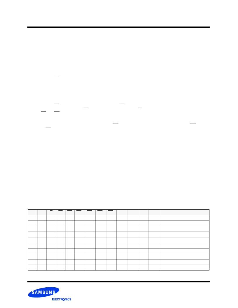
TRUTH TABLE
K
ZZ
G
SS
SW
SWa
SWb
SWc
SWd
DQa
DQb
DQc
DQd
Operation
X
H
X
X
X
X
X
X
X
Hi-Z
Hi-Z
Hi-Z
Hi-Z
Power Down Mode. No Operation
X
L
H
X
X
X
X
X
X
Hi-Z
Hi-Z
Hi-Z
Hi-Z
Output Disabled. No Operation
↑
↑
L
L
H
X
X
X
X
X
Hi-Z
Hi-Z
Hi-Z
Hi-Z
Output Disabled. No Operation
L
L
L
H
X
X
X
X
D
OUT
D
OUT
D
OUT
D
OUT
Read Cycle
↑
↑
↑
↑
↑
↑
L
X
L
L
H
H
H
H
Hi-Z
Hi-Z
Hi-Z
Hi-Z
No Bytes Written
L
X
L
L
L
H
H
H
D
IN
Hi-Z
Hi-Z
Hi-Z
Write first byte
L
X
L
L
H
L
H
H
Hi-Z
D
IN
Hi-Z
Hi-Z
Write second byte
L
X
L
L
H
H
L
H
Hi-Z
Hi-Z
D
IN
Hi-Z
Write third byte
L
X
L
L
H
H
H
L
Hi-Z
Hi-Z
Hi-Z
D
IN
Write fourth byte
L
X
L
L
L
L
L
L
D
IN
D
IN
D
IN
D
IN
Write all byte
相關(guān)PDF資料 |
PDF描述 |
|---|---|
| KM736FV4022 | 128Kx36 Synchronous SRAM(128Kx36位同步靜態(tài) RAM) |
| KM718V089 | 512Kx36 & 1Mx18 Synchronous SRAM |
| KM718FV4021H-5 | 128Kx36 & 256Kx18 Synchronous Pipelined SRAM |
| KM718FV4021H-6 | 128Kx36 & 256Kx18 Synchronous Pipelined SRAM |
| KM718FV4021H-7 | 128Kx36 & 256Kx18 Synchronous Pipelined SRAM |
相關(guān)代理商/技術(shù)參數(shù) |
參數(shù)描述 |
|---|---|
| KM718N | 制造商:FRONTIER 制造商全稱:Frontier Electronics. 功能描述:10mm Adjustable Unshielded IFT Coils |
| KM718N-LFR | 制造商:FRONTIER 制造商全稱:Frontier Electronics. 功能描述:10mm Adjustable Unshielded IFT Coils |
| KM718V089 | 制造商:SAMSUNG 制造商全稱:Samsung semiconductor 功能描述:512Kx36 & 1Mx18 Synchronous SRAM |
| KM718V789AT-60 | 制造商:Samsung Semiconductor 功能描述: |
| KM718V887 | 制造商:SAMSUNG 制造商全稱:Samsung semiconductor 功能描述:256Kx18 Synchronous SRAM |
發(fā)布緊急采購,3分鐘左右您將得到回復(fù)。