- 您現(xiàn)在的位置:買賣IC網(wǎng) > PDF目錄358013 > IT314 PULSE TRANSFORMER FOR GENERAL PURPOSE APPLICATION(S) PDF資料下載
參數(shù)資料
| 型號: | IT314 |
| 元件分類: | 脈沖/數(shù)據(jù)通信變壓器 |
| 英文描述: | PULSE TRANSFORMER FOR GENERAL PURPOSE APPLICATION(S) |
| 封裝: | ROHS COMPLIANT |
| 文件頁數(shù): | 2/3頁 |
| 文件大小: | 172K |
| 代理商: | IT314 |

> Components
> IT series
Explanations:
–
tr rise time at given load resistor R and 70% of the output pulse height.
–
Lp primary inductance measured at 1kHz (secondary coile open).
–
Lstr stray inductance measured at the secondary side, short circuit at the primary side. If there are several secondary coils only one at the time is connected (measuring frequency 10kHz).
–
The ignition current is a set peak value where the voltage drop over the coil resistance is still insignificant (mostly below 1V).
Pulse transformer selection table
IT 143
IT 153
IT 242
IT 243
IT 213
IT 233
IT 253
IT 312
IT 313
1:1:1
1:1:1
1:1:1
1:1:1
1:1:1
1:1:1
1:1:1
1:1:1
1:1:1
0.025
0.1
0.1
0.1
0.25
0.25
0.25
0.25
500
500
500
500
380
500
500
380
380
4
4
800
600
250
250
450
300
160
1200
450
0.6
1.4
0.9
15
9
2.5
2.5
6.5
3
1.1
21
200
120
75 0.75
85
20
45
45 0.55
35
6 0.33
3
3
10
10
7
7
40
7
6
30
27
02
02
02
02
02
02
02
02
02
14
14
1.5
1.5
0.75
0.8
1.4
0.8
0.55
2.7
0.4
3.2
3.2
2.5
6
6
9
1
0.8
1.4
0.8
0.4
1.3
1.3
4
13
3.2
2.5
2.5
6
1
2.4
24
24
1
0.6
3
IT 249
2:1:1
0.25
500
3.2
330
4
17
140
3.1
1.5
9
02
6
IT 154
IT 244
IT 234
IT 314
3:1:1
3:1:1
3:1:1
3:1:1
0.1
0.1
0.25
500
500
500
380
4
600
200
280
500
1.3
0.7
75
15
17
35
180
70
40
20
7.5
2.8
2.2
0.9
0.7
0.7
9
9
9
02
02
02
02
14
6
13
25
3.2
4
1
1
2
1
2.5
1.6
30
Pulse transformer
Turns ratio Ignition
Voltage
U
nom
[V]
Voltage
time area
U
p
[kV]
Rise
time
Inductance Resistance
L
p
L
str
[mH]
[μH]
Coupling
Input/Output
connections
Weight
current
capacitance
R
s
[Ω]
I
ign
[A]
V
0t
t
r
R
p
[Ω]
C
k
[Vμs]
[μs]
[pF]
[g]
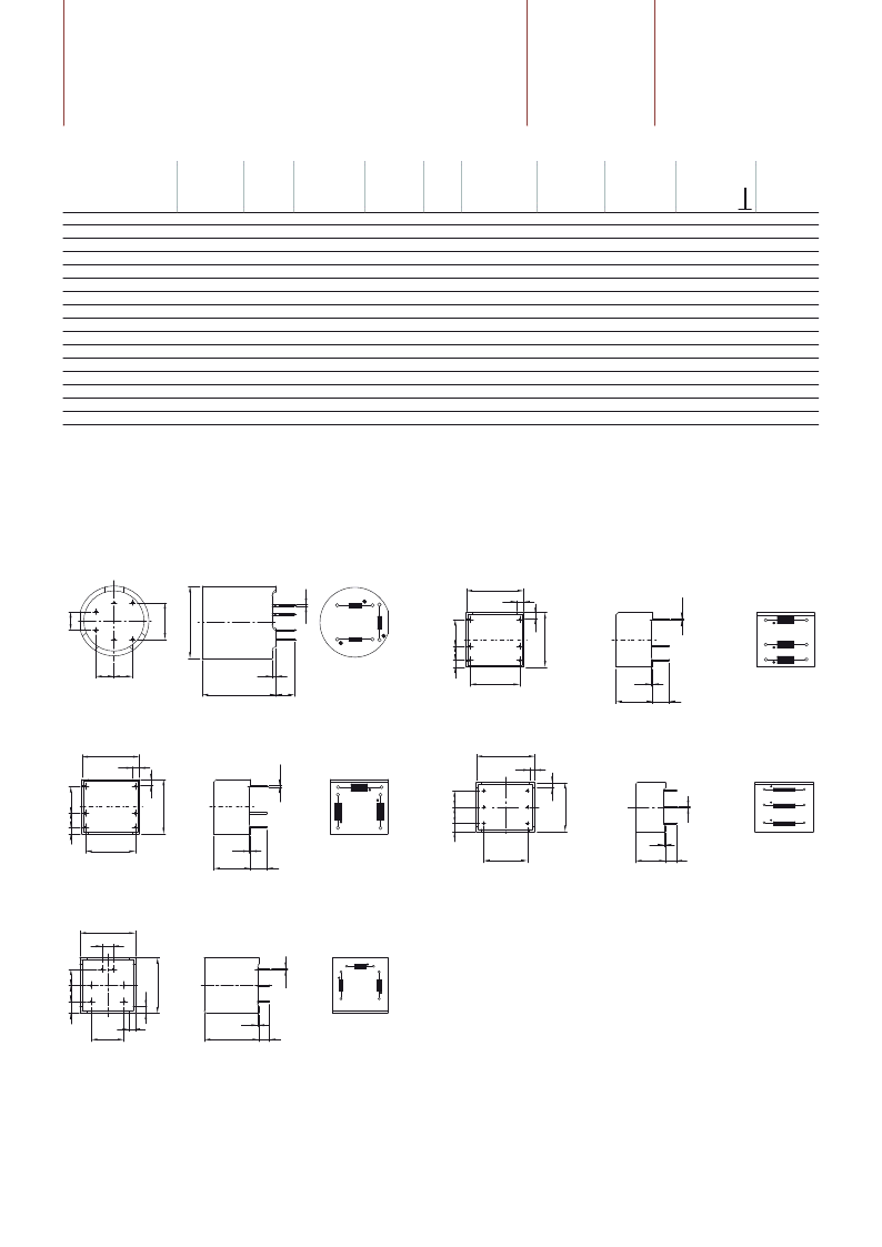
Mechanical data
IT 213
IT 243, IT 244, IT 249, IT 253
C
D
F
A
H
G
E
6
1
2
4
P
H
H
3
5
5
2
1
4
3
6
IT 143, IT 153, IT 154, IT 233, IT 234
L
C
D
F
A
H
G
E
L
B
1
3
2
6
Prim.
I
5
4
2
4
1
5
6
3
H
IT 312, IT 313, IT 314
K
C
D
F
A
H
G
E
L
B
3
2
4
5
Prim.
I
L
H
1
6
4
5
3
2
6
1
L
C
D
F
A
H
G
E
L
B
6
4
5
1
Prim.
K
I
2
3
5
3
6
2
1
4
IT 242
L
C
D
F
A
H
G
E
L
B
6
4
5
1
Prim.
K
I
2
3
5
3
6
4
2
1
相關PDF資料 |
PDF描述 |
|---|---|
| IT313 | PULSE TRANSFORMER FOR GENERAL PURPOSE APPLICATION(S) |
| IT312 | PULSE TRANSFORMER FOR GENERAL PURPOSE APPLICATION(S) |
| IT253 | PULSE TRANSFORMER FOR GENERAL PURPOSE APPLICATION(S) |
| IT249 | PULSE TRANSFORMER FOR GENERAL PURPOSE APPLICATION(S) |
| IT244 | PULSE TRANSFORMER FOR GENERAL PURPOSE APPLICATION(S) |
相關代理商/技術參數(shù) |
參數(shù)描述 |
|---|---|
| IT315 | 制造商:未知廠家 制造商全稱:未知廠家 功能描述:ISOTAB TRIACS ELECTRICALLY ISOLATED |
| IT315A | 制造商:未知廠家 制造商全稱:未知廠家 功能描述:ISOTAB TRIACS ELECTRICALLY ISOLATED |
| IT315B | 制造商:未知廠家 制造商全稱:未知廠家 功能描述:ISOTAB TRIACS ELECTRICALLY ISOLATED |
| IT315HA | 制造商:未知廠家 制造商全稱:未知廠家 功能描述:ISOTAB TRIACS ELECTRICALLY ISOLATED |
| IT315HX | 制造商:未知廠家 制造商全稱:未知廠家 功能描述:ISOTAB TRIACS ELECTRICALLY ISOLATED |
發(fā)布緊急采購,3分鐘左右您將得到回復。