- 您現(xiàn)在的位置:買賣IC網(wǎng) > PDF目錄360996 > ISO121BG Precision Low Cost ISOLATION AMPLIFIER PDF資料下載
參數(shù)資料
| 型號(hào): | ISO121BG |
| 元件分類: | 隔離放大器 |
| 英文描述: | Precision Low Cost ISOLATION AMPLIFIER |
| 中文描述: | 精密低成本隔離放大器 |
| 文件頁數(shù): | 7/16頁 |
| 文件大?。?/td> | 184K |
| 代理商: | ISO121BG |
7
ISO120/121
f
3 dB
≈
1.2
200k
150 pF
+
C
2
(
)
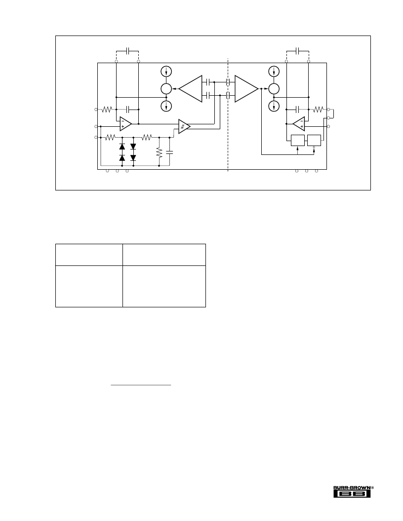
FIGURE 1. Block Diagram.
C
1
, C
2
ISO120/121
MODULATOR, DEMODULATOR
EXTERNAL CAPACITOR
EXTERNAL CLOCK
FREQUENCY RANGE
400kHz to 700kHz
200kHz to 400kHz
100kHz to 200kHz
50kHz to 100kHz
20kHz to 50kHz
10kHz to 20kHz
5kHz to 10kHz
none
500pF
1000pF
2200pF
4700pF
0.01
μ
F
0.022
μ
F
The value of the external modulator capacitor, C
, depends on
the frequency of the external clock signal. Table I lists
recommended values.
Synchronizing to a 400kHz to 700kHz
Square-Wave External Clock
At frequencies above 400kHz, an internal clamp and filter
provides signal conditioning so that a square-wave signal can
be used to directly drive the ISO120/121. A square-wave
external clock signal can be used to directly drive the ISO120/
121
ext osc
pin if: the signal is in the 400kHz to 700kHz
frequency range with a 25% to 75% duty cycle, and
±
3V to
±
20V level. Details of the internal clamp and filter circuitry
are shown in Figure 1.
Synchronizing to a 10% to 90%
Duty-cycle External Clock
With the addition of the signal conditioning circuit shown in
Figure 2, any 10% to 90% duty-cycle square-wave signal can
be used to drive the ISO120/121 ext osc pin. With the values
shown, the circuit can be driven by a 4Vp-p TTL signal. For
a higher or lower voltage input, increase or decrease the 1k
resistor, R
X
, proportionally. e.g. for a
±
4V square wave
(8Vp-p) R
X
should be increased to 2k
.
The value of C
used in the Figure 2 circuit depends on the
frequency of the external clock signal. Table II shows recom-
mended capacitor values.
Note: For external clock frequencies below 400kHz, external
modulator/demodulator capacitors are required on the
ISO120/121 as before.
TABLE I. Recommended ISO120/121 External Modulator/
Demodulator Capacitor Values vs External Clock
Frequency.
The value of the external demodulator capacitor, C
, depends
on the value of the external modulator capacitor. To assure
stability, C
must be greater than 0.8 C
. A larger value for
C
2
will decrease bandwidth and improve stability:
Where:
f
–3dB
≈
–3dB bandwidth of ISO amp with external C
2
(Hz)
C
2
= External demodulator capacitor (f)
For example, with C
= 0.01
μ
F, the f
–3dB
bandwidth of the
ISO120/121 is approximately 600Hz.
1pF
1pF
1pF
1pF
S/H
G = 1
S/H
G = 6
Sense
V
OUT
Signal
Com 2
Gnd 2 –V
S2
+V
S2
Gnd 1 –V
S1
+V
S1
Signal
Com 1
Ext
Osc
V
IN
C
1H
C
1L
C
1
(1)
200k
150pF
A1
100μA
Sense
200μA
X
100μA
Sense
200μA
200k
150pF
C
2L
C
2H
C
2
(1)
X
A2
Isolation Barrier
NOTE: (1) Optional. See text.
30k
16k
16k
50pF
相關(guān)PDF資料 |
PDF描述 |
|---|---|
| ISO121G | Precision Low Cost ISOLATION AMPLIFIER |
| ISO130 | |
| ISO130P | Amplifier. Other |
| ISO130PB | Amplifier. Other |
| ISO130U | Amplifier. Other |
相關(guān)代理商/技術(shù)參數(shù) |
參數(shù)描述 |
|---|---|
| ISO121G | 功能描述:隔離放大器 Prec Lo Cost Iso Amp RoHS:否 制造商:Texas Instruments 輸入補(bǔ)償電壓:1.5 mV 共模抑制比(最小值):95 dB 帶寬:60 KHz 工作電源電壓:3.3 V 電源電流:8 mA 工作溫度范圍:- 40 C to + 105 C 安裝風(fēng)格:SMD/SMT 封裝 / 箱體:SOP-8 封裝:Tube |
| ISO122 | 制造商:BB 制造商全稱:BB 功能描述:Precision Lowest Cost ISOLATION AMPLIFIER |
| ISO122JP | 功能描述:隔離放大器 Precision Low Cost Isolation Amp RoHS:否 制造商:Texas Instruments 輸入補(bǔ)償電壓:1.5 mV 共模抑制比(最小值):95 dB 帶寬:60 KHz 工作電源電壓:3.3 V 電源電流:8 mA 工作溫度范圍:- 40 C to + 105 C 安裝風(fēng)格:SMD/SMT 封裝 / 箱體:SOP-8 封裝:Tube |
| ISO122JP | 制造商:Texas Instruments 功能描述:AMP PRECISION ISOLATION DIP16 122 |
| ISO122JPE4 | 功能描述:隔離放大器 Precision Low Cost Isolation Amp RoHS:否 制造商:Texas Instruments 輸入補(bǔ)償電壓:1.5 mV 共模抑制比(最小值):95 dB 帶寬:60 KHz 工作電源電壓:3.3 V 電源電流:8 mA 工作溫度范圍:- 40 C to + 105 C 安裝風(fēng)格:SMD/SMT 封裝 / 箱體:SOP-8 封裝:Tube |
發(fā)布緊急采購(gòu),3分鐘左右您將得到回復(fù)。