- 您現(xiàn)在的位置:買賣IC網(wǎng) > PDF目錄9229 > ISL22343UFR20Z-TK (Intersil)IC POT DGTL 256TP LN LP 20-QFN PDF資料下載
參數(shù)資料
| 型號: | ISL22343UFR20Z-TK |
| 廠商: | Intersil |
| 文件頁數(shù): | 15/18頁 |
| 文件大小: | 0K |
| 描述: | IC POT DGTL 256TP LN LP 20-QFN |
| 標(biāo)準(zhǔn)包裝: | 1,000 |
| 系列: | XDCP™ |
| 接片: | 256 |
| 電阻(歐姆): | 50k |
| 電路數(shù): | 4 |
| 溫度系數(shù): | 標(biāo)準(zhǔn)值 ±45 ppm/°C |
| 存儲器類型: | 非易失 |
| 接口: | I²C(設(shè)備位址) |
| 電源電壓: | 2.25 V ~ 5.5 V |
| 工作溫度: | -40°C ~ 125°C |
| 安裝類型: | 表面貼裝 |
| 封裝/外殼: | 20-VQFN 裸露焊盤 |
| 供應(yīng)商設(shè)備封裝: | 20-QFN 裸露焊盤(5x5) |
| 包裝: | 帶卷 (TR) |

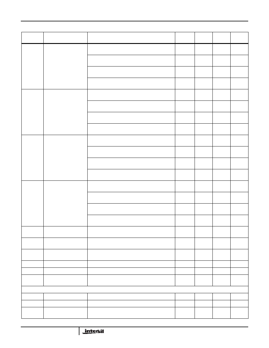
6
FN6423.1
March 13, 2008
ISB
VCC Current (Standby)
VCC = +5.5V, V- = -5.5V @ +85°C, I
2C interface in
standby state
0.5
2.0
A
VCC = +5.5V, V- = -5.5V @ +125°C, I
2C interface in
standby state
1.0
4.0
A
VCC = +2.25V, V- = -2.25V @ +85°C, I
2C interface in
standby state
0.2
1.0
A
VCC = +2.25V, V- = -2.25V @ +125°C, I
2C interface in
standby state
0.5
2.0
A
IV-SB
V- Current (Standby)
V- = -5.5V, VCC = +5.5V @ +85°C, I
2C interface in
standby state
-4.0
-0.7
A
V- = -5.5V, VCC = +5.5V @ +125°C, I
2C interface in
standby state
-5.0
-1.5
A
V- = -2.25V, VCC = +2.25V @ +85°C, I
2C interface in
standby state
-2.0
-0.3
A
V- = -2.25V, VCC = +2.25V @ +125°C, I
2C interface in
standby state
-3.0
-0.4
A
ISD
VCC Current (Shutdown)
VCC = +5.5V, V- = -5.5V @ +85°C, I
2C interface in
standby state
0.5
2.0
A
VCC = +5.5V, V- = -5.5V @ +125°C, I
2C interface in
standby state
1.0
4.0
A
VCC = +2.25V, V- = -2.25V @ +85°C, I
2C interface in
standby state
0.2
1.0
A
VCC = +2.25V, V- = -2.25V @ +125°C, I
2C interface in
standby state
0.5
2.0
A
IV-SD
V- Current (Shutdown)
V- = -5.5V, VCC = +5.5V @ +85°C, I
2C interface in
standby state
-4.0
-0.7
A
V- = -5.5V, VCC = +5.5V @ +125°C, I
2C interface in
standby state
-5.0
-1.5
A
V- = -2.25V, VCC = +2.25V @ +85°C, I
2C interface in
standby state
-2.0
-0.3
A
V- = -2.25V, VCC = +2.25V @ +125°C, I
2C interface in
standby state
-3.0
-0.4
A
ILkgDig
Leakage Current, at Pins
A0, A1, A2, SDA, and SCL
Voltage at pin from GND to VCC
-1
1
A
tWRT
(Note 19)
DCP Wiper Response
Time
SCL falling edge of last bit of DCP data byte to wiper
new position
1.5
s
tShdnRec
(Note 19)
DCP Recall Time from
Shutdown Mode
SCL falling edge of last bit of ACR data byte to wiper
stored position and RH connection
1.5
s
Vpor
Power-on Recall Voltage
Minimum VCC at which memory recall occurs
1.9
2.1
V
VCCRamp
VCC Ramp Rate
0.2
V/ms
tD
Power-up Delay
VCC above Vpor, to DCP Initial Value Register recall
completed, and I2C Interface in standby state
5ms
EEPROM SPECIFICATION
EEPROM Endurance
1,000,000
Cycles
EEPROM Retention
Temperature T
≤ +55°C50
Years
tWC
(Note 20)
Non-volatile Write Cycle
Time
12
20
ms
Operating Specifications Over the recommended operating conditions unless otherwise specified. (Continued)
SYMBOL
PARAMETER
TEST CONDITIONS
MIN
(Note 21)
TYP
(Note 5)
MAX
(Note 21)
UNIT
ISL22343
相關(guān)PDF資料 |
PDF描述 |
|---|---|
| MS3450L28-9SX | CONN RCPT 12POS WALL MNT W/SCKT |
| MS3450L28-9SW | CONN RCPT 12POS WALL MNT W/SCKT |
| MS27467T23F55SA | CONN PLUG 55POS STRAIGHT W/SCKT |
| ISL22343TFR20Z-TK | IC POT DGTL 256TP LN LP 20-QFN |
| MS27474T24B35PD | CONN RCPT 128POS JAM NUT W/PINS |
相關(guān)代理商/技術(shù)參數(shù) |
參數(shù)描述 |
|---|---|
| ISL22343UFV20Z | 功能描述:數(shù)字電位計 IC 256 TAP FL RNG IND QD I2C DCP 20LD RoHS:否 制造商:Maxim Integrated 電阻:200 Ohms 溫度系數(shù):35 PPM / C 容差:25 % POT 數(shù)量:Dual 每 POT 分接頭:256 弧刷存儲器:Volatile 緩沖刷: 數(shù)字接口:Serial (3-Wire, SPI) 描述/功能:Dual Volatile Low Voltage Linear Taper Digital Potentiometer 工作電源電壓:1.7 V to 5.5 V 電源電流:27 uA 最大工作溫度:+ 125 C 安裝風(fēng)格:SMD/SMT 封裝 / 箱體:TQFN-16 封裝:Reel |
| ISL22343UFV20Z-TK | 功能描述:數(shù)字電位計 IC 259 TAP FL RNG IND QD I2C DCP 20LD RoHS:否 制造商:Maxim Integrated 電阻:200 Ohms 溫度系數(shù):35 PPM / C 容差:25 % POT 數(shù)量:Dual 每 POT 分接頭:256 弧刷存儲器:Volatile 緩沖刷: 數(shù)字接口:Serial (3-Wire, SPI) 描述/功能:Dual Volatile Low Voltage Linear Taper Digital Potentiometer 工作電源電壓:1.7 V to 5.5 V 電源電流:27 uA 最大工作溫度:+ 125 C 安裝風(fēng)格:SMD/SMT 封裝 / 箱體:TQFN-16 封裝:Reel |
| ISL22343WFR20Z | 功能描述:數(shù)字電位計 IC 263 TAP FL RNG IND QD I2C DCP 5X5 RoHS:否 制造商:Maxim Integrated 電阻:200 Ohms 溫度系數(shù):35 PPM / C 容差:25 % POT 數(shù)量:Dual 每 POT 分接頭:256 弧刷存儲器:Volatile 緩沖刷: 數(shù)字接口:Serial (3-Wire, SPI) 描述/功能:Dual Volatile Low Voltage Linear Taper Digital Potentiometer 工作電源電壓:1.7 V to 5.5 V 電源電流:27 uA 最大工作溫度:+ 125 C 安裝風(fēng)格:SMD/SMT 封裝 / 箱體:TQFN-16 封裝:Reel |
| ISL22343WFR20Z-TK | 功能描述:數(shù)字電位計 IC 266 TAP FL RNG IND QD I2C DCP 5X5 RoHS:否 制造商:Maxim Integrated 電阻:200 Ohms 溫度系數(shù):35 PPM / C 容差:25 % POT 數(shù)量:Dual 每 POT 分接頭:256 弧刷存儲器:Volatile 緩沖刷: 數(shù)字接口:Serial (3-Wire, SPI) 描述/功能:Dual Volatile Low Voltage Linear Taper Digital Potentiometer 工作電源電壓:1.7 V to 5.5 V 電源電流:27 uA 最大工作溫度:+ 125 C 安裝風(fēng)格:SMD/SMT 封裝 / 箱體:TQFN-16 封裝:Reel |
| ISL22343WFV20Z | 功能描述:數(shù)字電位計 IC 257 TAP FL RNG IND QD I2C DCP 20LD RoHS:否 制造商:Maxim Integrated 電阻:200 Ohms 溫度系數(shù):35 PPM / C 容差:25 % POT 數(shù)量:Dual 每 POT 分接頭:256 弧刷存儲器:Volatile 緩沖刷: 數(shù)字接口:Serial (3-Wire, SPI) 描述/功能:Dual Volatile Low Voltage Linear Taper Digital Potentiometer 工作電源電壓:1.7 V to 5.5 V 電源電流:27 uA 最大工作溫度:+ 125 C 安裝風(fēng)格:SMD/SMT 封裝 / 箱體:TQFN-16 封裝:Reel |
發(fā)布緊急采購,3分鐘左右您將得到回復(fù)。