- 您現(xiàn)在的位置:買賣IC網(wǎng) > PDF目錄360971 > IRPT2051 (International Rectifier) Integrated Power Stage for 2.2kW Motor Drives(2.2kW 馬達(dá)驅(qū)動器的集成功率單元) PDF資料下載
參數(shù)資料
| 型號: | IRPT2051 |
| 廠商: | International Rectifier |
| 英文描述: | Integrated Power Stage for 2.2kW Motor Drives(2.2kW 馬達(dá)驅(qū)動器的集成功率單元) |
| 中文描述: | 集成功率級為2.2kW的電機(jī)驅(qū)動器(2.2kW的馬達(dá)驅(qū)動器的集成功率單元) |
| 文件頁數(shù): | 5/12頁 |
| 文件大小: | 126K |
| 代理商: | IRPT2051 |
page 5
IRPT2051
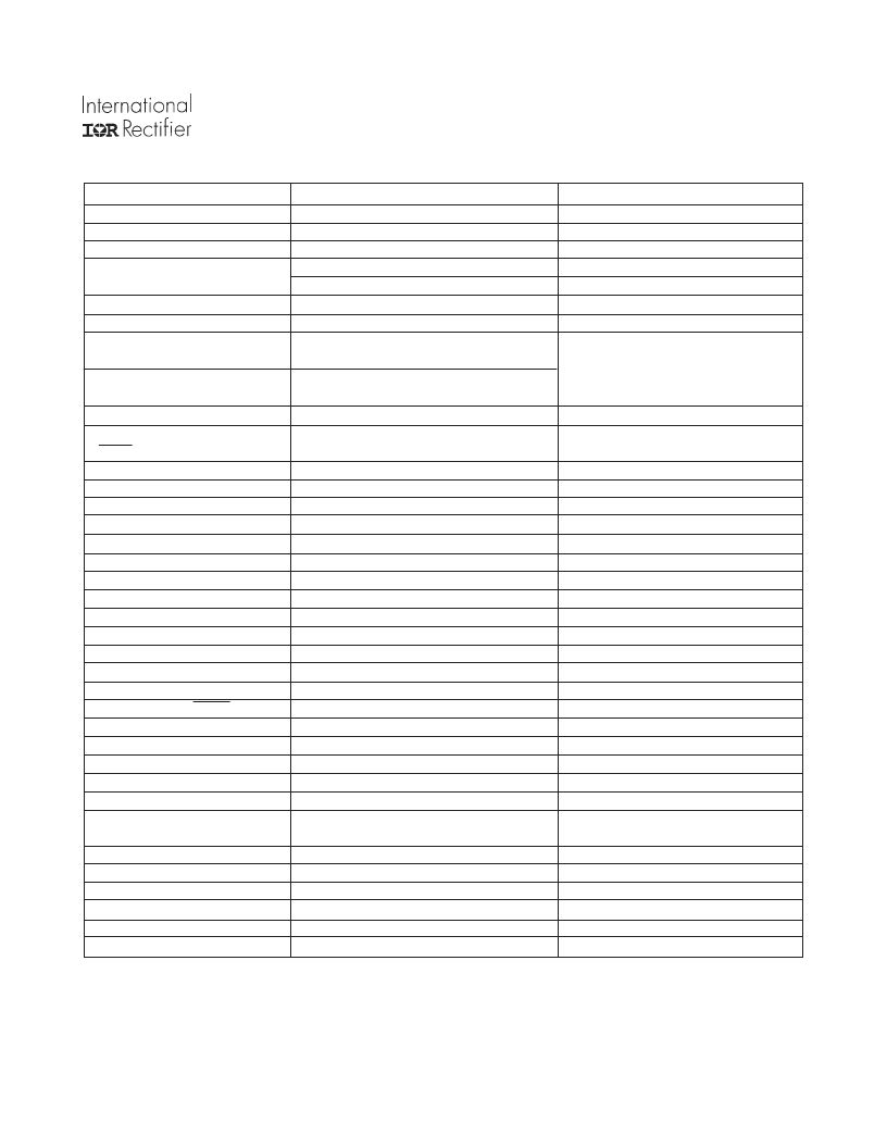
PARAMETERS
Input Power
Voltage
Frequency
Input current
VALUES
CONDITIONS
380V, -15%, 480V + 10%
50 - 60Hz
8.26A rms @ nominal output
125 A peak
T
A
= 40°C, R
thSA
= 0.59°C/W
Initial bus capacitor charging
Output
Voltage
Nominal motor hp (kW)
Power
0 - 480V rms
3hp (2.2 kW) nominal full load power
150% overload for 1 minute
5.90A rms nominal full load current
8.85A rms 150% overload for 1 minute
defined by external PWM control
R
thSA
= 0.59°C/W,
V
in
= 460V AC, f
PWM
= 4kHz,
f
°
= 60Hz, T
A
= 40°C,
Z
thSA
limits DT
c
to 10°C during overload
Nominal motor current
Control
IN1...IN6, (PWM), IN7 (Brake),
RESET
STOP
Pulse deadtime
Minimum input pulse width
Protection
Output current trip level
Earth fault current trip level
Overtemperature trip level
Overvoltage trip level
Maximum DC link voltage
Short circuit shutdown time
Feedback
Signals
Current feedback (IFB)
DC bus voltage feedback (VFB)
0.010V/V
BUS
typical
Fault feedback (FAULT)
On Board Power Supply
V
CC
V
DD
I
CC
+ I
DD
Brake
Current
Module
Isolation voltage
Operating case temperature
Mounting torque
System Environment
Ambient operating temp. range
Storage temp.range
Inputs
5V maximum, active low
CMOS, LSTTL compatible,
open collector
CMOS or LSTTL compatible
maximum set by controller
5V maximum, active high
0.2 μsec typical, set by IR2233
1.0 μsec
45A peak, ± 10%
50A, ± 10%
100°C, ± 5%
850V, ± 10%
760V
2.5 μsec typical
T
C
= 25°C
T
C
= 25°C
Case temperature
user to ensure rating not exceeded > 30 sec
output terminals shorted
0.025V/A
BUS
typical
T
C
= 25°C
T
C
= 25°C
5V maximum, active low
CMOS or LSTTL compatible
15V, ± 10%
5V, ± 5%
60 mA
available to user
10.5A
2500V rms
-25°C to 125°C
1 N-m
pin-to-baseplate isolation, 60Hz, 1 min.
95% RH max. (non-condensing)
M4 screw type
0 to 40°C
-25 to 60°C
95% RH max. (non-condensing)
Specifications
相關(guān)PDF資料 |
PDF描述 |
|---|---|
| IRPT4052 | |
| IRPT4052 | Integrated Power Stage for 5.5kW Motor Drives(5.5kW 馬達(dá)驅(qū)動器的集成功率單元) |
| IRPT5051 | |
| IRPT5051A | |
| IRPT5051 | Integrated Power Stage for 11kW Motor Drives(11kW 馬達(dá)驅(qū)動器的集成功率單元) |
相關(guān)代理商/技術(shù)參數(shù) |
參數(shù)描述 |
|---|---|
| IRPT2051A | 制造商:未知廠家 制造商全稱:未知廠家 功能描述: |
| IRPT2055 | 制造商:未知廠家 制造商全稱:未知廠家 功能描述: |
| IRPT2055A | 制造商:未知廠家 制造商全稱:未知廠家 功能描述: |
| IRPT2056 | 制造商:IRF 制造商全稱:International Rectifier 功能描述:Power Module for 3 hp Motor Drives |
| IRPT2056A | 制造商:IRF 制造商全稱:International Rectifier 功能描述:Power Module for 3 hp Motor Drives |
發(fā)布緊急采購,3分鐘左右您將得到回復(fù)。