- 您現(xiàn)在的位置:買賣IC網(wǎng) > PDF目錄384509 > IRP2166 (International Rectifier) PFC & BALLAST CONTROL IC PDF資料下載
參數(shù)資料
| 型號: | IRP2166 |
| 廠商: | International Rectifier |
| 元件分類: | 基準電壓源/電流源 |
| 英文描述: | PFC & BALLAST CONTROL IC |
| 中文描述: | 功率因數(shù)校正 |
| 文件頁數(shù): | 20/32頁 |
| 文件大小: | 616K |
| 代理商: | IRP2166 |
第1頁第2頁第3頁第4頁第5頁第6頁第7頁第8頁第9頁第10頁第11頁第12頁第13頁第14頁第15頁第16頁第17頁第18頁第19頁當前第20頁第21頁第22頁第23頁第24頁第25頁第26頁第27頁第28頁第29頁第30頁第31頁第32頁
IR2166 & (PbF)
20
www.irf.com
4
3
3uA
5
2
CPH
CT
RPH
RT
11
12
COM
LO
M2
R
CS
OSC
16
HO
M1
15
VS
C
CPH
C
T
Half-
Bridge
Output
I
LOAD
(+)
V
BUS
(-)
Load
Return
Half-
Bridge
Driver
IR2166
1.3V
S1
S4
Comp 4
10
13
VCC
CS
R1
C
CS
S3
Fault
Logic
V
BUS
R
T
R
PH
oscillate at the preheat frequency with 50% duty
cycle and with a dead-time which is set by the
value of the external timing capacitor, CT, and
internal deadtime resistor, RDT. Pin CPH is
disconnected from COM and an internal 3
μ
A
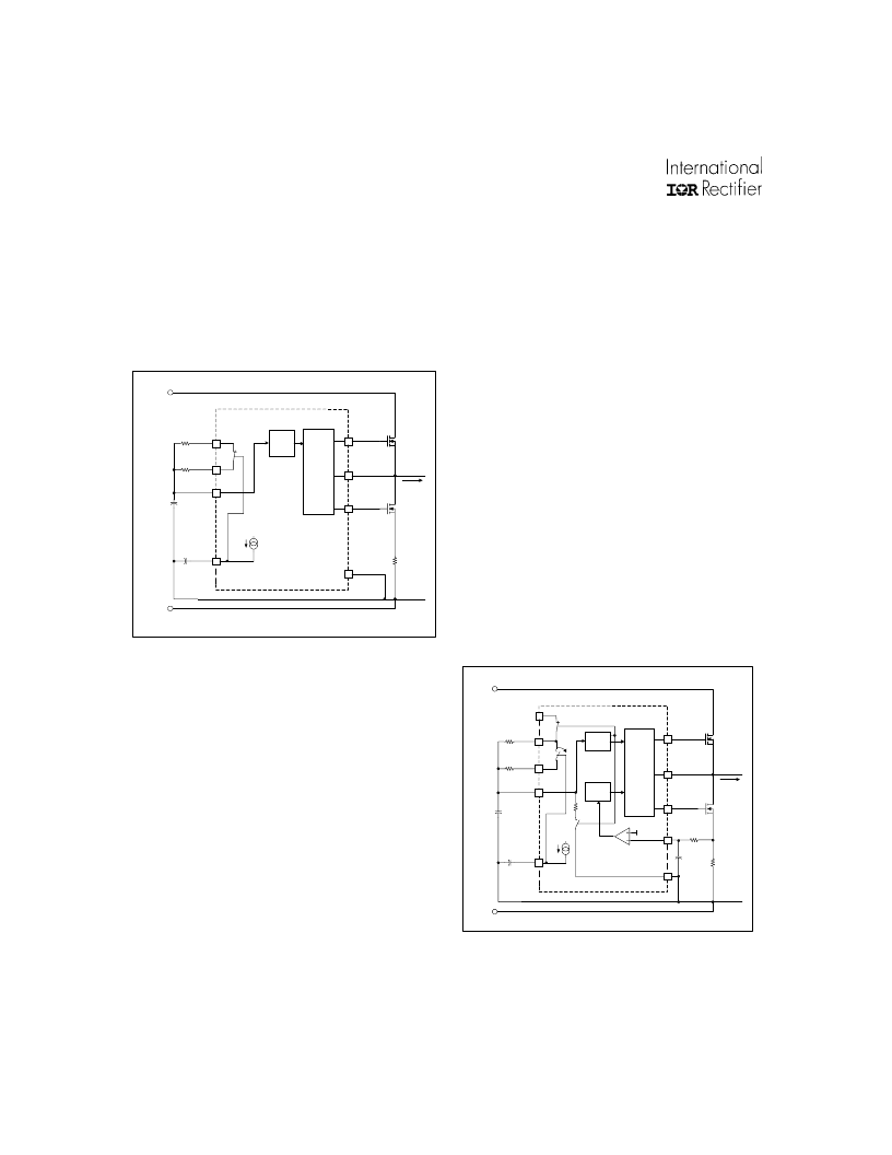
current source (Figure 3)
Figure 3, Preheat circuitry.
charges the external preheat timing capacitor
on CPH linearly. The over-current protection on
pin CS is disabled during preheat. The preheat
frequency is determined by the parallel
combination of resistors RT and RPH, together
with timing capacitor CT. CT charges and
discharges between 1/3 and 3/5 of VCC (see
Timing Diagram, page 9). CT is charged
exponentially through the parallel combination
of RT and RPH connected internally to VCC
through MOSFET S1. The charge time of CT
from 1/3 to 3/5 VCC is the on-time of the
respective output gate driver, HO or LO. Once
CT exceeds 3/5 VCC, MOSFET S1 is turned
off, disconnecting RT and RPH from VCC. CT is
then discharged exponentially through an
internal resistor, RDT, through MOSFET S3 to
COM. The discharge time of CT from 3/5 to 1/3
VCC is the dead-time (both off) of the output
gate drivers, HO and LO. The selected value of
CT together with RDT therefore program the
desired dead-time (see Design Equations, page
26, Equations 1 and 2). Once CT discharges
below 1/3 VCC, MOSFET S3 is turned off,
disconnecting RDT from COM, and MOSFET
S1 is turned on, connecting RT and RPH again
to VCC. The frequency remains at the preheat
frequency until the voltage on pin CPH exceeds
10V and the IC enters Ignition Mode. During the
preheat mode, the over-current protection
together with the fault counter are enabled. The
peak ignition current must not exceed the
maximum allowable current ratings of the output
stage MOSFETs. Should this voltage exceed the
internal threshold of 1.3V, the internal FAULT
Counter begins counting the sequential over-
current faults (See Timing Diagram). If the
number of over-current faults exceed 25, the IC
will enter FAULT mode and gate driver outputs
HO, LO and PFC will be latched low.
Figure 4, Ignition circuitry.
4
3
3uA
5
2
CPH
CT
RPH
RT
11
12
COM
LO
M2
RCS
OSC.
16
HO
M1
15
VS
R
T
C
CPH
Half-
Bridge
Output
I
LOAD
V
BUS
(+)
V
BUS
(-)
Load
Return
Half-
Bridge
Driver
IR2166
S4
R
PH
C
T
相關PDF資料 |
PDF描述 |
|---|---|
| IRPLDIM2a | Digitally Addressable DALI Dimming Ballast Reference Design |
| IRPLLNR3 | Universal Input Linear Fluorescent Ballast using the IR2167 |
| IRPT1061A | Power Module for 1 hp Motor Drives |
| IRPT3054A | Power Module for 5 hp Motor Drives |
| IRPT5051C | Integrated Power Stage for 15 hp Motor Drives |
相關代理商/技術參數(shù) |
參數(shù)描述 |
|---|---|
| IRP22N50A | 制造商:VISHAY 制造商全稱:Vishay Siliconix 功能描述:Power MOSFET |
| IRP22N50APBF | 制造商:VISHAY 制造商全稱:Vishay Siliconix 功能描述:Power MOSFET |
| IRP38L000 | 制造商:Amphenol PCD 功能描述:DIN-RAIL INTERFACE MODULE PRODUCT -SEE CATALOG - Bulk |
| IRP38R000 | 制造商:Amphenol PCD 功能描述:DIN-RAIL INTERFACE MODULE PRODUCT -SEE CATALOG - Bulk |
| IRP3F422 | 制造商:APEM 功能描述: 制造商:APEM 功能描述:IP67 SEALED PUSHBUTTON SWITCH |
發(fā)布緊急采購,3分鐘左右您將得到回復。