- 您現(xiàn)在的位置:買賣IC網(wǎng) > PDF目錄377521 > IRHF93130 (International Rectifier) HEXFET Transistor(HEXFET 晶體管) PDF資料下載
參數(shù)資料
| 型號(hào): | IRHF93130 |
| 廠商: | International Rectifier |
| 英文描述: | HEXFET Transistor(HEXFET 晶體管) |
| 中文描述: | 的HEXFET晶體管(之HEXFET晶體管) |
| 文件頁數(shù): | 3/8頁 |
| 文件大小: | 122K |
| 代理商: | IRHF93130 |
IRHF9130, IRHF93130, JANSR-, JANSF-, 2N7389 Device
REVEW ONLY
www.irf.com
3
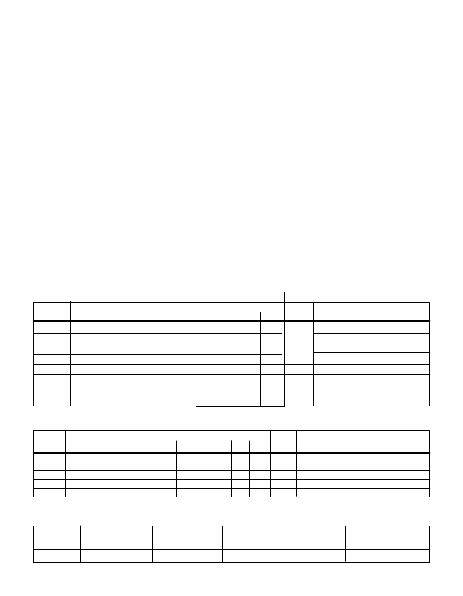
Table 1. Low Dose Rate
IRHF9130 IRHF93130
Parameter
100K Rads (Si) 300K Rads (Si)
Units
MIN
MAX
MIN
MAX
BV
DSS
Drain-to-Source Breakdown Voltage -100 — -100 —
V
GS(th)
Gate Threshold Voltage
-2.0 -4.0 -2.0 -5.0
I
GSS
Gate-to-Source Leakage Forward — -100 — -100
I
GSS
Gate-to-Source Leakage Reverse — 100 — 100
I
DSS
Zero Gate Voltage Drain Current — -25 — -25
R
DS(on)1
Static Drain-to-Source
— 0.30 — 0.30
On-State Resistance One
V
SD
Diode Forward Voltage
— -3.0 — -3.0
Test Conditions
V
V
GS
= 0V, I
D
= -1.0mA
V
GS
= V
DS
, I
D
= -1.0mA
V
GS
= -20V
V
GS
= 20V
V
DS
=0.8 x Max Rating, V
GS
=0V
V
GS
= -12V, I
D
=-4.1A
nA
μA
W
V
TC = 25°C, IS = -6.5A,V
GS
= 0V
Radiation Performance of P-Channel Rad
Hard HEXFETs
International Rectifier Radiation Hardened HEXFETs
are tested to verify their hardness capability. The hard-
ness assurance program at International Rectifier com-
prises three radiation environments.
Every manufacturing lot is tested in a low dose rate
(total dose) environment per MIL-STD-750, test method
1019 condition A. International Rectifier has imposed
a standard gate condition of -12 volts per note 5 and a
V
bias condition equal to 80% of the device rated
voltage per note 6. Pre- and post- irradiation limits of
the devices irradiated to 1 x 10
5
Rads (Si) are identical
and are presented in Table 1, column 1, IRHF9130.
Post-irradiation limits of the devices irradiated to 3 x
10
5
Rads (Si) are presented in Table 1, column 2,
IRHF93130. The values in Table 1 will be met for ei-
ther of the two low dose rate test circuits that are used.
Both pre- and post-irradiation performance are tested
and specified using the same drive circuitry and test
conditions in order to provide a direct comparison. It
should be noted that at a radiation level of 3 x 10
5
Rads (Si) the only parametric limit change is V
GS(th)
maximum.
High dose rate testing may be done on a special re-
quest basis using a dose rate up to 1 x 10
12
Rads (Si)/
Sec (See Table 2).
International Rectifier radiation hardened P-Channel
HEXFETs are considered to be neutron-tolerant, as
stated in MIL-PRF-19500 Group D. International Rec-
tifier radiation hardened P-Channel HEXFETs have
been characterized in heavy ion Single Event Effects
(SEE) environments. Single Event Effects character-
ization is shown in Table 3.
Table 2. High Dose Rate
10
11
Rads (Si)/sec 10
12
Rads (Si)/sec
Min Typ Max
—
—
-80
Parameter
Drain-to-Source Voltage
Min Typ Max
Units
—
—
-80
Test Conditions
V
DSS
V
Applied drain-to-source voltage during
gamma-dot
Peak radiation induced photo-current
-160 A/μsec Rate of rise of photo-current
—
μH
Circuit inductance required to limit di/dt
IPP
di/dt
L1
—
—
0.1
-60
—
—
—
—
—
0.5
-60
—
—
—
A
-800
—
Table 3. Single Event Effects
LET (Si)
Fluence Range V
DS
Bias V
GS
Bias
Ion
(MeV/mg/cm
2
) (ions/cm
2
) (μm) (V) (V)
Cu 28
3x 10
5
~43 -100
5
Radiation Characteristics
相關(guān)PDF資料 |
PDF描述 |
|---|---|
| IRHG58110 | RADIATION HARDENED POWER MOSFET THRU-HOLE (MO-036) |
| IRHG53110 | RADIATION HARDENED POWER MOSFET THRU-HOLE (MO-036) |
| IRHG54110 | RADIATION HARDENED POWER MOSFET THRU-HOLE (MO-036) |
| IRHG57110 | RADIATION HARDENED POWER MOSFET THRU-HOLE (MO-036) |
| IRHG9110 | Thru-Hole Radiation Hardened Power MOSFET(100V,通孔安裝抗輻射功率MOSFET) |
相關(guān)代理商/技術(shù)參數(shù) |
參數(shù)描述 |
|---|---|
| IRHF93230 | 制造商:International Rectifier 功能描述:HEXFET, HIREL, RAD HARD,G4 - Bulk |
| IRHG110 | 制造商:未知廠家 制造商全稱:未知廠家 功能描述:TRANSISTOR | MOSFET | N-CHANNEL | 100V V(BR)DSS | 950MA I(D) | DIP |
| IRHG3110 | 制造商:IRF 制造商全稱:International Rectifier 功能描述:RADIATION HARDENED POWER MOSFET THRU-HOLE (MO-036AB) |
| IRHG3214 | 制造商:IRF 制造商全稱:International Rectifier 功能描述:RADIATION HARDENED POWER MOSFET THRU-HOLE |
| IRHG4110 | 制造商:IRF 制造商全稱:International Rectifier 功能描述:RADIATION HARDENED POWER MOSFET THRU-HOLE (MO-036AB) |
發(fā)布緊急采購,3分鐘左右您將得到回復(fù)。