- 您現(xiàn)在的位置:買賣IC網(wǎng) > PDF目錄360953 > IRG4RC10STRR TRANSISTOR | IGBT | N-CHAN | 600V V(BR)CES | 8A I(C) | TO-252AA PDF資料下載
參數(shù)資料
| 型號: | IRG4RC10STRR |
| 英文描述: | TRANSISTOR | IGBT | N-CHAN | 600V V(BR)CES | 8A I(C) | TO-252AA |
| 中文描述: | 晶體管| IGBT的|正陳| 600V的五(巴西)國際消費電子展| 8A條一(c)|至252AA |
| 文件頁數(shù): | 2/8頁 |
| 文件大?。?/td> | 150K |
| 代理商: | IRG4RC10STRR |
IRG4RC10S
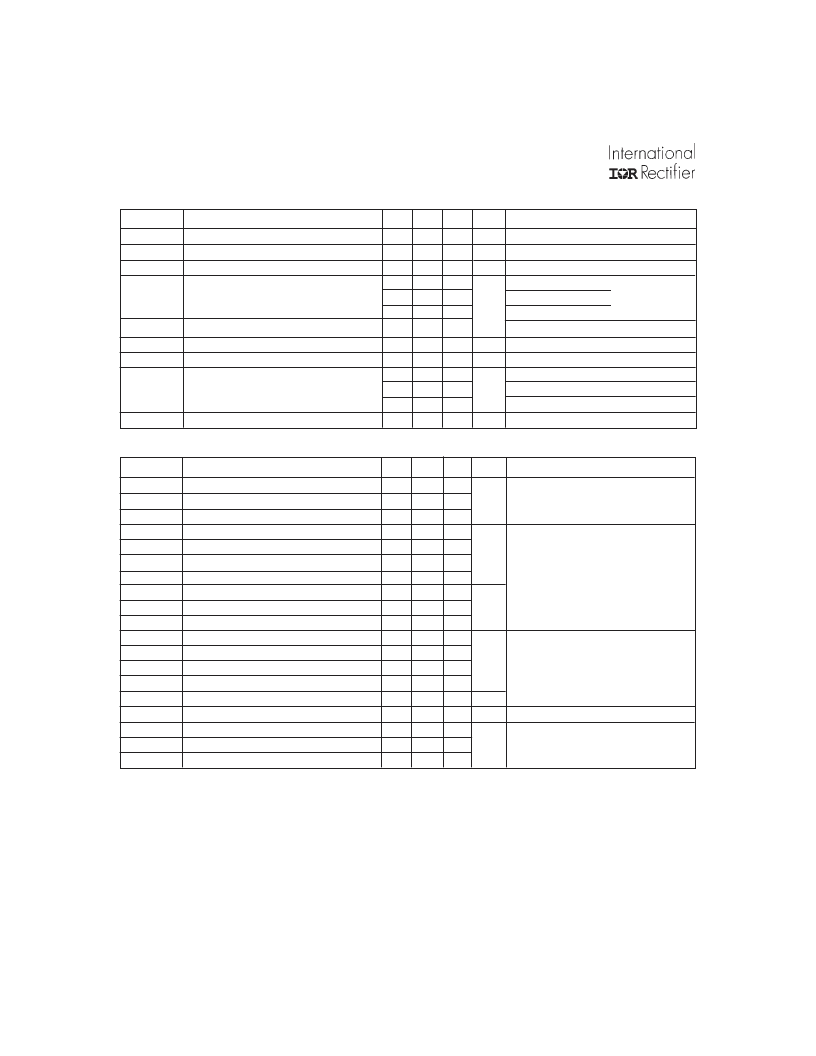
Electrical Characteristics @ T
J
= 25°C (unless otherwise specified)
2
www.irf.com
Parameter
Collector-to-Emitter Breakdown Voltage
Emitter-to-Collector Breakdown Voltage
V
(BR)CES
/
T
J
Temperature Coeff. of Breakdown Voltage
Min. Typ. Max. Units
600
—
18
—
—
0.64
—
1.58
—
2.05
—
1.68
3.0
—
—
-9.5
3.7
5.5
—
—
—
—
—
—
—
—
Conditions
V
(BR)CES
V
(BR)ECS
—
—
—
1.7
—
—
6.0
—
—
250
2.0
1000
±100
V
V
V
GE
= 0V, I
C
= 250μA
V
GE
= 0V, I
C
= 1.0A
V
GE
= 0V, I
C
= 1.0mA
I
C
= 8.0A V
GE
= 15V
I
C
= 14A
I
C
= 8.0A , T
J
= 150°C
V
CE
= V
GE
, I
C
= 250μA
mV/°C V
CE
= V
GE
, I
C
= 250μA
S
V
CE
= 100V, I
C
= 8.0A
V
GE
= 0V, V
CE
= 600V
V
GE
= 0V, V
CE
= 10V, T
J
= 25°C
V
GE
= 0V, V
CE
= 600V, T
J
= 150°C
nA
V
GE
= ±20V
V/°C
V
CE(ON)
Collector-to-Emitter Saturation Voltage
See Fig.2, 5
V
GE(th)
V
GE(th)
/
T
J
g
fe
Gate Threshold Voltage
Temperature Coeff. of Threshold Voltage
Forward Transconductance
I
GES
Gate-to-Emitter Leakage Current
Parameter
Total Gate Charge (turn-on)
Gate - Emitter Charge (turn-on)
Gate - Collector Charge (turn-on)
Turn-On Delay Time
Rise Time
Turn-Off Delay Time
Fall Time
Turn-On Switching Loss
Turn-Off Switching Loss
Total Switching Loss
Turn-On Delay Time
Rise Time
Turn-Off Delay Time
Fall Time
Total Switching Loss
Internal Emitter Inductance
Input Capacitance
Output Capacitance
Reverse Transfer Capacitance
Min. Typ. Max. Units
—
15
—
2.4
—
6.5
—
25
—
28
—
630
—
710 1100
—
0.14
—
2.58
—
2.72
—
24
—
31
—
810
—
1300
—
3.94
—
7.5
—
280
—
30
—
4.0
Conditions
Q
g
Q
ge
Q
gc
t
d(on)
t
r
t
d(off)
t
f
E
on
E
off
E
ts
t
d(on)
t
r
t
d(off)
t
f
E
ts
L
E
C
ies
C
oes
C
res
Notes:
22
3.6
9.8
—
—
950
I
C
= 8.0A
V
CC
= 400V
V
GE
= 15V
nC
See Fig. 8
T
J
= 25°C
I
C
= 8.0A, V
CC
= 480V
V
GE
= 15V, R
G
= 100
Energy losses include "tail"
See Fig. 9, 10, 14
—
—
4.3
—
—
—
—
—
—
—
—
—
mJ
T
J
= 150°C,
I
C
= 8.0A, V
CC
= 480V
V
GE
= 15V, R
G
= 100
Energy losses include "tail"
See Fig. 11, 14
Measured 5mm from package
V
GE
= 0V
V
CC
= 30V
= 1.0MHz
mJ
nH
pF
See Fig. 7
I
CES
Zero Gate Voltage Collector Current
V
μA
Switching Characteristics @ T
J
= 25°C (unless otherwise specified)
ns
ns
Pulse width
≤
80μs; duty factor
≤
0.1%.
Repetitive rating; V
GE
= 20V, pulse width limited by
max. junction temperature. ( See fig. 13b )
V
CC
= 80%(V
CES
), V
GE
= 20V, L = 10μH, R
G
= 100
,
(See fig. 13a)
Repetitive rating; pulse width limited by maximum
junction temperature.
Pulse width 5.0μs, single shot.
Powered by ICminer.com Electronic-Library Service CopyRight 2003
相關(guān)PDF資料 |
PDF描述 |
|---|---|
| IRG4ZC71KD | |
| IRG4ZH70UD | |
| IRG4ZH71KD | |
| IRGAC30F | TRANSISTOR | IGBT | N-CHAN | 600V V(BR)CES | 23A I(C) | TO-204AE |
| IRGAC30U | TRANSISTOR | IGBT | N-CHAN | 600V V(BR)CES | 17A I(C) | TO-204AE |
相關(guān)代理商/技術(shù)參數(shù) |
參數(shù)描述 |
|---|---|
| IRG4RC10STRRPBF | 功能描述:IGBT 晶體管 600V DC-1 KHZ (STD) DISCRETE IGBT RoHS:否 制造商:Fairchild Semiconductor 配置: 集電極—發(fā)射極最大電壓 VCEO:650 V 集電極—射極飽和電壓:2.3 V 柵極/發(fā)射極最大電壓:20 V 在25 C的連續(xù)集電極電流:150 A 柵極—射極漏泄電流:400 nA 功率耗散:187 W 最大工作溫度: 封裝 / 箱體:TO-247 封裝:Tube |
| IRG4RC10U | 制造商:International Rectifier 功能描述:IGBT |
| IRG4RC10UD | 功能描述:IGBT W/DIODE 600V 8.5A D-PAK RoHS:否 類別:分離式半導(dǎo)體產(chǎn)品 >> IGBT - 單路 系列:- 標準包裝:30 系列:GenX3™ IGBT 類型:PT 電壓 - 集電極發(fā)射極擊穿(最大):1200V Vge, Ic時的最大Vce(開):3V @ 15V,100A 電流 - 集電極 (Ic)(最大):200A 功率 - 最大:830W 輸入類型:標準 安裝類型:通孔 封裝/外殼:TO-247-3 供應(yīng)商設(shè)備封裝:PLUS247?-3 包裝:管件 |
| IRG4RC10UDPBF | 功能描述:IGBT 晶體管 600V ULTRAFAST 8-60 KHZ COPACK IGBT RoHS:否 制造商:Fairchild Semiconductor 配置: 集電極—發(fā)射極最大電壓 VCEO:650 V 集電極—射極飽和電壓:2.3 V 柵極/發(fā)射極最大電壓:20 V 在25 C的連續(xù)集電極電流:150 A 柵極—射極漏泄電流:400 nA 功率耗散:187 W 最大工作溫度: 封裝 / 箱體:TO-247 封裝:Tube |
| IRG4RC10UDTR | 制造商:International Rectifier 功能描述:Trans IGBT Chip N-CH 600V 8.5A 3-Pin(2+Tab) DPAK T/R |
發(fā)布緊急采購,3分鐘左右您將得到回復(fù)。