- 您現(xiàn)在的位置:買賣IC網(wǎng) > PDF目錄360891 > IP1845AJ Current-Mode SMPS Controller PDF資料下載
參數(shù)資料
| 型號(hào): | IP1845AJ |
| 英文描述: | Current-Mode SMPS Controller |
| 中文描述: | 電流模式開關(guān)電源控制器 |
| 文件頁(yè)數(shù): | 4/6頁(yè) |
| 文件大小: | 72K |
| 代理商: | IP1845AJ |
LAB
SEME
IP1844A SERIES
IP1845A SERIES
Semelab plc.
Telephone (01455) 556565. Telex: 341927. Fax (01455) 552612.
Prelim. 2/95
IP1844A , IP1845A
IP2844A , IP2845A
Min.
Typ.
IP3844A
IP3845A
Typ.
Parameter
Test Conditions
1
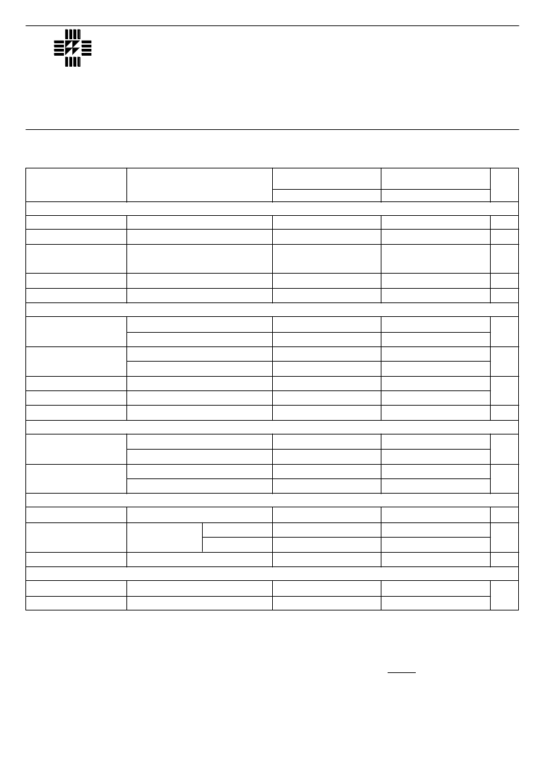
CURRENT SENSE SECTION
Max.
Min.
Max.
Units
2.85
0.9
3
1
3.15
1.1
60
70
–2
150
–10
300
0.1
1.5
13.5
13.5
50
50
0.7
0.4
2.2
13
12
150
150
1.1
14.5
7.8
8.5
7
16
8.4
10
7.6
17.5
9
11.5
8.2
0.3
11
14
34
0.5
15
17
40
30
46
48
50
0
2.85
0.9
3
1
3.15
1.1
60
70
–2
150
–10
300
0.1
1.5
13.5
13.5
50
50
0.7
0.4
2.2
13
12
150
150
1.1
15
7.8
9
7
16
8.4
10
7.6
17
9
11
8.2
0.3
11
14
34
0.5
15
17
40
30
47
48
50
0
Gain
Maximum Input Signal
Supply Voltage
Rejection
Input Bias Current
Delay to Output
Output Low Level
Output High Level
Rise Time
Fall Time
UVLO Saturation
Upper Threshold
(V
CC
)
Lower Threshold
(V
CC
)
Start–up Current
Operating Supply
Current
V
CC
Zener Voltage
Maximum Duty Cycle
Minimum Duty Cycle
See Notes 2,3
V
PIN1
= 5V
(Note 2)
V
C
= 12V to 25V
I
SINK
= 20mA
I
SINK
= 200mA
I
SOURCE
= 20mA
I
SOURCE
= 200mA
C
L
= 1nF
C
L
= 1nF
V
CC
= 6V
UNDER–VOLTAGE LOCKOUT SECTION
I
L
= 1mA
IP1844A Series
IP1845A Series
IP1844A Series
IP1845A Series
V
PIN2
= 0V
V
PIN3
= 0V
I
CC
= 25mA
PWM SECTION
IP1844A Series
IP1845A Series
V/V
V
dB
μ
A
ns
V
V
ns
V
V
V
mA
mA
V
%
NOTES
ELECTRICAL CHARACTERISTICS
(Over Full Operating Temperature Range unless otherwise stated)
OUTPUT SECTION
TOTAL STANDBY CURRENT
1. Test Conditions unless otherwise stated:
V
CC
= 15V* , R
T
= 10k
, C
T
= 3.3nF , f = 52kHz.
*Adjust V
CC
above start threshold before setting at
required level.
All specifications apply over the full operating temperature
range unless otherwise stated.
(See Ordering Information for further details).
2. Parameter measured at trip point of latch with
V
PIN2
= 0V
3. Gain defined as:
A =
V
PIN3
0
≤
V
PIN3
≤
0.8
V
PIN1
相關(guān)PDF資料 |
PDF描述 |
|---|---|
| IP3845AD-14 | Current-Mode SMPS Controller |
| IP3845AD-8 | Current-Mode SMPS Controller |
| IP3845AJ | Current-Mode SMPS Controller |
| IP2844AD-14 | Current-Mode SMPS Controller |
| IP2844AD-8 | Current-Mode SMPS Controller |
相關(guān)代理商/技術(shù)參數(shù) |
參數(shù)描述 |
|---|---|
| IP1845J | 制造商:未知廠家 制造商全稱:未知廠家 功能描述:Analog IC |
| IP1845J/883B | 制造商:未知廠家 制造商全稱:未知廠家 功能描述:Current-Mode SMPS Controller |
| IP18RS-N1 | 制造商:Sibille 功能描述:INSUL SUPADRIV NO.1 |
| IP18RS-N2 | 制造商:Sibille 功能描述:INSUL SUPADRIV NO.2 |
| IP191 | 制造商:IBase Technology (USA) Inc. 功能描述:BP, BUTTERFLY BACKPLANE FOR MB875 PCI EXPANSION, (ROHS) - Bulk |
發(fā)布緊急采購(gòu),3分鐘左右您將得到回復(fù)。