- 您現(xiàn)在的位置:買賣IC網(wǎng) > PDF目錄360862 > INA118P Precision, Low Power INSTRUMENTATION AMPLIFIER PDF資料下載
參數(shù)資料
| 型號: | INA118P |
| 元件分類: | 測量放大器 |
| 英文描述: | Precision, Low Power INSTRUMENTATION AMPLIFIER |
| 中文描述: | 精密低功耗儀表放大器 |
| 文件頁數(shù): | 8/11頁 |
| 文件大小: | 242K |
| 代理商: | INA118P |
8
INA118
APPLICATION INFORMATION
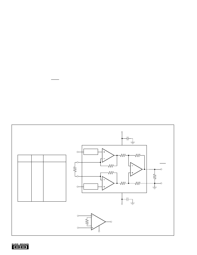
Figure 1 shows the basic connections required for operation
of the INA118. Applications with noisy or high impedance
power supplies may require decoupling capacitors close to
the device pins as shown.
The output is referred to the output reference (Ref) terminal
which is normally grounded. This must be a low-impedance
connection to assure good common-mode rejection. A resis-
tance of 12
in series with the Ref pin will cause a typical
device to degrade to approximately 80dB CMR (G = 1).
SETTING THE GAIN
Gain of the INA118 is set by connecting a single external
resistor, R
G
, connected between pins 1 and 8:
Commonly used gains and resistor values are shown in
Figure 1.
The 50k
term in Equation 1 comes from the sum of the two
internal feedback resistors of A
1
and A
2
. These on-chip
metal film resistors are laser trimmed to accurate absolute
values. The accuracy and temperature coefficient of these
resistors are included in the gain accuracy and drift specifi-
cations of the INA118.
(1)
G
=
1
+
50k
R
G
FIGURE 1. Basic Connections.
DESIRED
GAIN
R
G
(
)
NEAREST 1% R
G
(
)
1
2
5
NC
NC
49.9k
12.4k
5.62k
2.61k
1.02k
511
249
100
49.9
24.9
10
4.99
50.00k
12.50k
5.556k
2.632k
1.02k
505.1
251.3
100.2
50.05
25.01
10.00
5.001
10
20
50
100
200
500
1000
2000
5000
10000
NC: No Connection.
The stability and temperature drift of the external gain
setting resistor, R
G
, also affects gain. R
G
’s contribution to
gain accuracy and drift can be directly inferred from the gain
equation (1). Low resistor values required for high gain can
make wiring resistance important. Sockets add to the wiring
resistance which will contribute additional gain error (possi-
bly an unstable gain error) in gains of approximately 100 or
greater.
DYNAMIC PERFORMANCE
The typical performance curve “Gain vs Frequency” shows
that, despite its low quiescent current, the INA118 achieves
wide bandwidth, even at high gain. This is due to the
current-feedback topology of the INA118. Settling time also
remains excellent at high gain.
The INA118 exhibits approximately 3dB peaking at 500kHz
in unity gain. This is a result of its current-feedback topol-
ogy and is not an indication of instability. Unlike an op amp
with poor phase margin, the rise in response is a predictable
+6dB/octave due to a response zero. A simple pole at
300kHz or lower will produce a flat passband unity gain
response.
A
1
A
2
A
3
6
60k
60k
60k
60k
7
4
3
8
1
2
V
IN
V
IN
R
G
V+
V–
INA118
G = 1 +50k
R
G
–
+
5
Ref
Over-Voltage
Protection
25k
25k
Over-Voltage
Protection
Load
V
O
= G (V
IN
– V
IN
)
+
–
0.1μF
0.1μF
+
–
V
O
R
G
Also drawn in simplified form:
INA118
Ref
V
O
V
IN
–
V
IN
+
相關(guān)PDF資料 |
PDF描述 |
|---|---|
| INA118PB | RES,THKF,68.0,1.0%,100PPM,0.125W |
| INA118U | Precision, Low Power INSTRUMENTATION AMPLIFIER |
| INA121PA | CAP, 220UF @ 50V |
| INA121 | Precision Gain of 5 Instrumentation Amplifier |
| INA121P | Precision Gain of 5 Instrumentation Amplifier |
相關(guān)代理商/技術(shù)參數(shù) |
參數(shù)描述 |
|---|---|
| INA118P | 制造商:Texas Instruments 功能描述:IC AMP INSTRUMENTATION DIP8 118 |
| INA118P | 制造商:Texas Instruments 功能描述:AMP INSTRUMENTATION 800KHZ PDIP8 制造商:Texas Instruments 功能描述:AMP, INSTRUMENTATION, 800KHZ, PDIP8 制造商:Texas Instruments 功能描述:AMP, INSTRUMENTATION, 800KHZ, PDIP8; No. of Amplifiers:1; Input Offset Voltage:125V; Bandwidth:800kHz; Supply Voltage Range: 1.35V to 18V; Amplifier Case Style:DIP; No. of Pins:8; Amplifier Output:Single Ended; CMRR:125dB; Slew ;RoHS Compliant: Yes |
| INA118PB | 功能描述:儀表放大器 Precision Low Power Instrumentation Amp RoHS:否 制造商:Texas Instruments 通道數(shù)量: 輸入補償電壓:150 V 可用增益調(diào)整: 最大輸入電阻:10 kOhms 共模抑制比(最小值):88 dB 工作電源電壓:2.7 V to 36 V 電源電流:200 uA 最大工作溫度:+ 125 C 最小工作溫度:- 40 C 封裝 / 箱體:MSOP-8 封裝:Bulk |
| INA118PB | 制造商:Texas Instruments 功能描述:IC AMP INSTRUMENTATION |
| INA118PB | 制造商:Texas Instruments 功能描述:IC AMP INSTRUMENTATION PDIP8 118 |
發(fā)布緊急采購,3分鐘左右您將得到回復。