- 您現(xiàn)在的位置:買賣IC網(wǎng) > PDF目錄383107 > ILD766 (SIEMENS A G) BIDIRECTIONAL INPUT DARLINGTON OPTOCOUPLERS PDF資料下載
參數(shù)資料
| 型號: | ILD766 |
| 廠商: | SIEMENS A G |
| 元件分類: | 光電耦合器 |
| 英文描述: | BIDIRECTIONAL INPUT DARLINGTON OPTOCOUPLERS |
| 中文描述: | 2 CHANNEL DARLINGTON OUTPUT OPTOCOUPLER |
| 封裝: | DIP-8 |
| 文件頁數(shù): | 1/3頁 |
| 文件大小: | 65K |
| 代理商: | ILD766 |
5–1
FEATURES
Internal R
High Current Transfer Ratios, V
IL/ILD766-1: 500% at I
IL/ILD766-2: 500% at I
BV
CEO
>60 V
AC or Polarity Insensitive Inputs
Built-In Reverse Polarity Input
Industry Standard DIP Package
Underwriters Lab File #E52744
DESCRIPTION
BE
for Better Stability
CE
=5
V
F
F
=2 mA
=1.0 mA
Protection
The IL/ILD766 are bidirectional input optically cou-
pled isolators. They consist of two Gallium Ars-
enide infrared emitting diodes coupled to a silicon
NPN photodarlington per channel.
The IL766 are single channel optocouplers. The
ILD766 has two isolated channels in a single DIP
package. They are designed for applications
requiring detection or monitoring of AC
Maximum Ratings
Emitter
(Each Channel)
Continuous Forward Current.........................60 mA
Power Dissipation at 25
°
C
Single Channel.......................................200 mW
Dual Channel............................................90 mW
Derate Linearly from 25
°
C
Single Channel...................................2.6 mW/
Dual Channel......................................1.2 mW/
Detector
(Each Channel
)
Collector-Emitter Breakdown Voltage ..............60 V
Collector-Base Breakdown Voltage .................70 V
Power Dissipation at 25
°
C .........................100 mW
Derate Linearly from 25
°
C ...................1.33 mW/
Package
Isolation Test Voltage
(t= 1 sec.)................... 7500 VAC
Isolation Resistance
T
A
=25
°
C
........................................................≥
T
A
=100
°
C
.....................................................≥
Total Power Dissipation at 25
(LED Plus Detector)
Single Channel.......................................250 mW
Dual Channel..........................................400 mW
Derate Linearly from 25
°
C
Single Channel...................................3.3 mW/
Dual Channel ....................................5.3 mW/
Creepage............................................... 7 mm min.
Clearance............................................... 7 mm min.
Comparative Tracking Index per
DIN IEC 112/VDE303, part 1.........................175
Storage Temperature....................–55
Operating Temperature................–55
Lead Soldering Time at 260
signals.
°
°
C
C
°
C
PK
/5300 VAC
RMS
10
10
12
11
°
C Ambient
°
°
C
C
°
°
C to +150
C to +100
°
°
C
C
°
C .................... 10 sec.
Electrical Characteristics
(T
A
=25
°
C)
Sym
Min
Typ
Max.
Unit
Condition
Emitter
Forward Voltage
V
F
1.2
1.5
V
I
F
=
±
10 mA
Detector
Breakdown Voltage,
Collector-Emitter
Collector-Base
Leakage Current,
Collector-Emitter
BV
BV
CEO
CBO
60
60
75
90
V
V
I
I
C
C
=1 mA
=10
μ
A
I
CEO
10
100
nA
V
CE
=10 V
Package
Saturation Voltage,
Collector-Emitter
DC Current Transfer
Ratio
IL766/ILD766-1
V
CEsat
1.0
V
I
I
F
C
=
=10 mA
±
10 mA,
IL766-2
CTR
500
500
%
%
I
V
I
F
V
V
I
F
R
F
=
CE
=
CE
±
2 mA,
=5 V
±
1.0 mA,
=5 V
=10 V,
±
2 mA,
=100
Rise Time, Fall Time
100
μ
s
CC
=
L
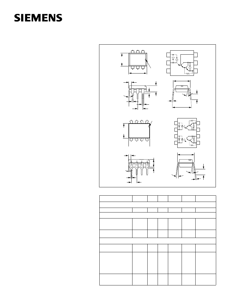
Dimensions in inches (mm)
1
2
3
6
5
4
Base
Collector
Emitter
Anode/
Cathode
Cathode/
Anode
NC
Emitter
Collector
Collector
Emitter
1
2
3
4
8
7
6
5
Anode/
Cathode
Cathode/
Anode
Anode/
Cathode
Cathode/
Anode
Pin One ID.
.255 (6.48)
.268 (6.81)
3
4
6
5
.379 (9.63)
.390 (9.91)
.030 (.76)
.045 (1.14)
4
°
Typ.
.100 (2.54)Typ.
10
°
Typ.
3
°
–9
°
.305 Typ.
(7.75) Typ.
.018 (.46)
.022 (.56)
.008 (.20)
.012 (.30)
.115 (2.92)
.135 (3.43)
1
2
8
7
.130 (3.30)
.150 (3.81)
.030 (.76 )
.040 (1.02)
.010 (.25)
.014 (.35)
.300 (7.62)
.347 (8.82)
.110 (2.79)
.150 (3.81)
.130 (3.30)
.150 (3.81)
.020 (.051) min.
.031 (0.80)
.035 (0.90)
.100 (2.54) Typ.
.300 (7.62)
Typ.
.039
(1.00)
min.
.018 (0.45)
.022 (0.55)
.335 (8.50)
.343 (8.70)
6
5
4
1
2
3
18
°
Typ.
4
°
Typ.
.248 (6.30)
.256 (6.50)
Pin One
I.D.
Dual Channel
Single Channel
SINGLE CHANNEL
DUAL CHANNEL
BIDIRECTIONAL INPUT
DARLINGTON OPTOCOUPLERS
IL766
ILD766
相關PDF資料 |
PDF描述 |
|---|---|
| IL766 | SMT Rotary Dip |
| ILH100 | HERMETIC PHOTOTRANSISTOR OPTOCOUPLER |
| ILH200 | HERMETIC PHOTOTRANSISTOR DUAL CHANNEL OPTOCOUPLER |
| ILQ32 | PHOTODARLINGTON OPTOCOUPLER |
| ILX103A | 3000-pixel CCD Linear Image Sensor (B/W) |
相關代理商/技術參數(shù) |
參數(shù)描述 |
|---|---|
| ILD766-1 | 功能描述:晶體管輸出光電耦合器 Photodarlington Out Dual CTR >500% RoHS:否 制造商:Vishay Semiconductors 輸入類型:DC 最大集電極/發(fā)射極電壓:70 V 最大集電極/發(fā)射極飽和電壓:0.4 V 絕緣電壓:5300 Vrms 電流傳遞比:100 % to 200 % 最大正向二極管電壓:1.65 V 最大輸入二極管電流:60 mA 最大集電極電流:100 mA 最大功率耗散:100 mW 最大工作溫度:+ 110 C 最小工作溫度:- 55 C 封裝 / 箱體:DIP-4 封裝:Bulk |
| ILD766-2 | 功能描述:晶體管輸出光電耦合器 Photodarlington Out Dual CTR >500% RoHS:否 制造商:Vishay Semiconductors 輸入類型:DC 最大集電極/發(fā)射極電壓:70 V 最大集電極/發(fā)射極飽和電壓:0.4 V 絕緣電壓:5300 Vrms 電流傳遞比:100 % to 200 % 最大正向二極管電壓:1.65 V 最大輸入二極管電流:60 mA 最大集電極電流:100 mA 最大功率耗散:100 mW 最大工作溫度:+ 110 C 最小工作溫度:- 55 C 封裝 / 箱體:DIP-4 封裝:Bulk |
| ILE4260-2 | 制造商:IKSEMICON 制造商全稱:IK Semicon Co., Ltd 功能描述:Power Voltage Regulator 5 V/500mA with Low Drop-out Voltage(analog to TLE4260 -2, Siemens) |
| ILE4260-2_1 | 制造商:IKSEMICON 制造商全稱:IK Semicon Co., Ltd 功能描述:Power Voltage Regulator 5 V/500mA with Low Drop-out Voltage(analog to TLE4260 -2, Siemens) |
| ILE4260-2_11 | 制造商:IKSEMICON 制造商全稱:IK Semicon Co., Ltd 功能描述:5-V Low-Drop Voltage Regulator |
發(fā)布緊急采購,3分鐘左右您將得到回復。