- 您現(xiàn)在的位置:買賣IC網(wǎng) > PDF目錄379217 > ILC6380AP-50 (Impala Linear Corporation) Rectangular Industrial Connector Housing; Series:C-146; No. of Contacts:24; Gender:Female; Body Material:Aluminum Alloy; Connecting Termination:Screw; Features:Spring Cover; For Use With:C146 Rectangular Circular Connectors RoHS Compliant: Yes PDF資料下載
參數(shù)資料
| 型號(hào): | ILC6380AP-50 |
| 廠商: | Impala Linear Corporation |
| 元件分類: | 圓形連接器 |
| 英文描述: | Rectangular Industrial Connector Housing; Series:C-146; No. of Contacts:24; Gender:Female; Body Material:Aluminum Alloy; Connecting Termination:Screw; Features:Spring Cover; For Use With:C146 Rectangular Circular Connectors RoHS Compliant: Yes |
| 中文描述: | 采用SOT - 89 -向上雙路降壓模式可關(guān)斷開(kāi)關(guān) |
| 文件頁(yè)數(shù): | 5/6頁(yè) |
| 文件大小: | 186K |
| 代理商: | ILC6380AP-50 |
SOT-89 Step-up Dual-Mode Switcher with Shutdown
Impala Linear Corporation
5
(408) 574-3939
www.impalalinear.com
Sept 1999
ILC6380/1 1.4
0.5mA. The only difference between the ILC6380 and ILC6381
parts is that the 6381 is configured to drive an external transistor
as the switch element. Since larger transistors can be selected for
this element, higher effective loads can be regulated.
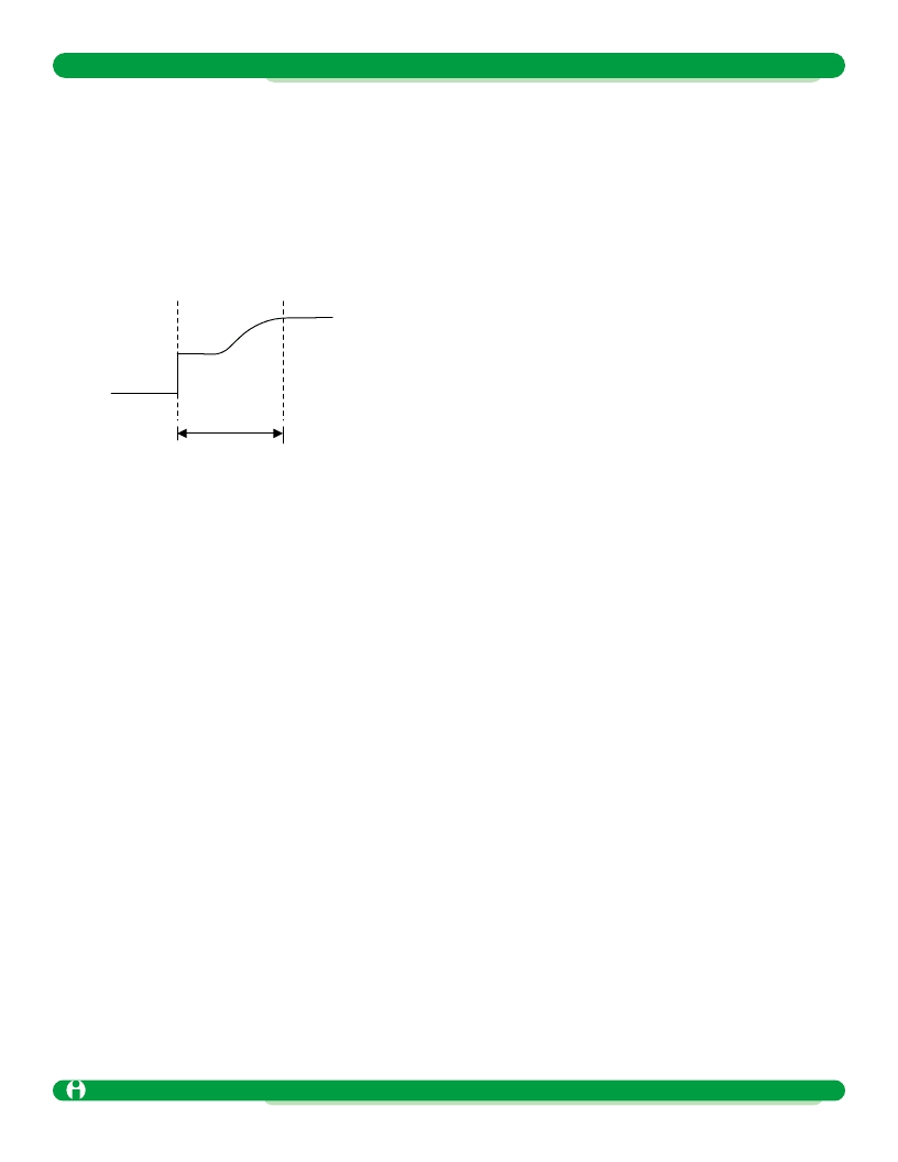
Start-up Mode
The ILC6380 has an internal soft-start mode which suppresses
ringing or overshoot on the output during start-up. The following
diagram illustrates this start-up condition’s typical performance:
External Components and Layout Consideration
The ILC6380 is designed to provide a complete DC-DC convertor
solution with a minimum of external components. Ideally, only
three externals are required: the inductor, a pass diode, and an
output capacitor.
The inductor needs to be of low DC Resistance type, typically 1
value. Toroidal wound inductors have better field containment (less
high frequency noise radiated out) but tend to be more expensive.
Some manufacturers like Coilcraft have new bobbin-wound induc-
tors with shielding included, which may be an ideal fit for these
applications. Contact the manufacturer for more information.
The inductor size needs to be in the range of 47mH to 1mH. In
general, larger inductor sizes deliver less current, so the load cur-
rent will determine the inductor size used.
For load currents higher than 10mA, use an inductor from 47mH
to 100mH. [
The 100mH inductor shown in the datasheet is the
most typical used for this application.
]
For load currents of around 5mA, such as pagers, use an inductor
in the range of 100mH to 330mH. 220mH is the most typical value
used here.
For lighter loads, an inductor of up to 1mH can be used. The use
of a larger inductor will increase overall conversion efficiency, due
to the reduction in switching currents through the device.
For the ILC6381, using an external transistor, the use of a 47mH
inductor is recommended based on our experience with the part.
Note that these values are recommended for both 50kHz and
100kHz operation. If using the ILC6380 or ILC6381 at 180kHz,
the inductor size can be reduced to approximately half of these
stated values.
The capacitor should, in general, always be tantalum type, as tan-
talum has much better ESR and temperature stability than other
capacitor types. NEVER use electrolytics or chemical caps, as the
C-value changes below 0×C so much as to make the overall
design unstable.
Different C-values will directly impact the ripple seen on the output
at a given load current, due to the direct charge-to-voltage rela-
tionship of this element. Different C-values will also indirectly affect
system reliability, as the lifetime of the capacitor can be degraded
by constant high current influx and outflux. Running a capacitor
near its maximum rated voltage can deteriorate lifetime as well;
this is especially true for tantalum caps which are particularly sen-
sitive to overvoltage conditions.
In general, then, this capacitor should always be 47mF, Tantalum,
16V rating.
The diode must be of shottkey type for fast recovery and minimal
loss. A diode rated at greater than 200mA and maximum voltage
greater than 30V is recommended for the fastest switching time
and best reliability over time. Different diodes may introduce dif-
ferent levels of high frequency switching noise into the output
waveform, so trying out several sources may make the most
sense for your system.
For the IL6381, much of the component selection is as described
above, with the addition of the external NPN transistor and the
base drive network. The transistor needs to be of NPN type, and
should be rated for currents of 2A or more. [
This translates to
lower effective on resistance and, therefore, higher overall effi-
ciencies.
] The base components should remain at 1k
and
3300pF; any changes need to be verified prior to implementation.
As for actual physical component layout, in general, the more
compact the layout is, the better the overall performance will be. It
is important to remember that everything in the circuit depends on
a common and solid ground reference. Ground bounce can direct-
ly affect the output regulation and presents difficult behavior to
predict. Keeping all ground traces wide will eliminate ground
bounce problems.
It is also critical that the ground pin of C
L
and the V
SS
pin of the
device be the same point on the board, as this capacitor serves
two functions: that of the output load capacitor, and that of the
input supply bypass capacitor.
Layouts for DC-DC converter designs are critical for overall per-
formance, but following these simple guidelines can simplify the
task by avoiding some of the more common mistakes made in
these cases. Once actual performance is completed, though, be
sure to double-check the design on actual manufacturing proto-
type product to verify that nothing has changed which can affect
the performance.
V
IN
- V
f
V
OUT MIN
T
SOFT-START
(~10msec)
t = 0
相關(guān)PDF資料 |
PDF描述 |
|---|---|
| ILC6380BP-25 | Pushbutton Switch; Illumination:Illuminated; Actuator Style:Round; Actuator Diameter:0.16"; Circuitry:SPST-NO; Switch Operation:On-(On); Switch Terminals:Through Hole; Contact Current Max:3A; Leaded Process Compatible:Yes RoHS Compliant: Yes |
| ILC6380BP-33 | SOT-89 STEP-UP DUAL-MODE SWITCHER WITH SHUTDOWN |
| ILC6380BP-50 | SOT-89 STEP-UP DUAL-MODE SWITCHER WITH SHUTDOWN |
| ILC6380CP-25 | SOT-89 STEP-UP DUAL-MODE SWITCHER WITH SHUTDOWN |
| ILC6380CP-33 | SOT-89 STEP-UP DUAL-MODE SWITCHER WITH SHUTDOWN |
相關(guān)代理商/技術(shù)參數(shù) |
參數(shù)描述 |
|---|---|
| ILC6380AP50X | 功能描述:直流/直流開(kāi)關(guān)轉(zhuǎn)換器 RoHS:否 制造商:STMicroelectronics 最大輸入電壓:4.5 V 開(kāi)關(guān)頻率:1.5 MHz 輸出電壓:4.6 V 輸出電流:250 mA 輸出端數(shù)量:2 最大工作溫度:+ 85 C 安裝風(fēng)格:SMD/SMT |
| ILC6380BP-25 | 制造商:IMPALA 制造商全稱:IMPALA 功能描述:SOT-89 STEP-UP DUAL-MODE SWITCHER WITH SHUTDOWN |
| ILC6380BP-33 | 制造商:IMPALA 制造商全稱:IMPALA 功能描述:SOT-89 STEP-UP DUAL-MODE SWITCHER WITH SHUTDOWN |
| ILC6380BP33X | 功能描述:直流/直流開(kāi)關(guān)轉(zhuǎn)換器 RoHS:否 制造商:STMicroelectronics 最大輸入電壓:4.5 V 開(kāi)關(guān)頻率:1.5 MHz 輸出電壓:4.6 V 輸出電流:250 mA 輸出端數(shù)量:2 最大工作溫度:+ 85 C 安裝風(fēng)格:SMD/SMT |
| ILC6380BP-50 | 制造商:Rochester Electronics LLC 功能描述:- Bulk |
發(fā)布緊急采購(gòu),3分鐘左右您將得到回復(fù)。