- 您現(xiàn)在的位置:買賣IC網(wǎng) > PDF目錄360752 > ICS615 Set-Top Box Clock Source PDF資料下載
參數(shù)資料
| 型號(hào): | ICS615 |
| 英文描述: | Set-Top Box Clock Source |
| 中文描述: | 機(jī)頂盒時(shí)鐘源 |
| 文件頁(yè)數(shù): | 3/4頁(yè) |
| 文件大小: | 57K |
| 代理商: | ICS615 |
ICS615
Set-Top Box Clock Source
MDS 615 A
Integrated Circuit Systems, Inc.525 Race StreetSan JoseCA95126(408)295-9800telwww.icst.com
3
Revision 052098
Printed 11/15/00
PRELIMINARY INFORMAT ION
ICRO
C
LOC K
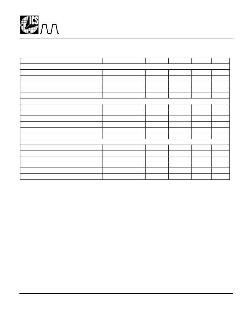
Parameter
ABSOLUTE MAXIMUM RATINGS (note 1)
Supply voltage, VDD
Inputs and Clock Outputs
Ambient Operating Temperature
Soldering Temperature
Storage temperature
DC CHARACTERISTICS (VDD = 5.0V unless noted)
Operating Voltage, VDD
Output High Voltage, VOH
Output Low Voltage, VOL
Output High Voltage, VOH, CMOS level
Operating Supply Current, IDD
Short Circuit Current
AC CHARACTERISTICS (VDD = 5.0V unless noted)
Input Clock
Output Clock Rise Time
Output Clock Fall Time
Output Clock Duty Cycle
Skew between any two outputs
Maximum Absolute Jitter, short term
Conditions
Minimum
Typical
Maximum
Units
Referenced to GND
Referenced to GND
7
V
V
°C
°C
°C
-0.5
0
VDD+0.5
70
260
150
Max of 10 seconds
-65
3.00
2.4
5.50
V
V
V
V
IOH=-4mA
IOL=4mA
IOH=-4mA
No Load
0.4
VDD-0.4
30
±30
mA
mA
13.5
1.5
1.5
50
MHz
ns
ns
%
ns
ps
0.4 to 2.4V, CL=25pF
2.4 to 0.4V, CL=25pF
At 1.4V
2.5
2.5
55
1
45
250
Electrical Specifications
Note:
Stresses beyond those listed under Absolute Maximum Ratings could cause permanent damage to the device. Prolonged
exposure to levels above the operating limits but below the Absolute Maximums may affect device reliability.
External Components
The ICS615 requires a minimum number of external components for proper operation. A decoupling
capacitor of 0.1μF should be connected between VDD and GND on pins 7 and 2, as close to the ICS615
as possible. A series termination resistor of 33
may be used for the clock outputs. The normal use is with a
clock input into pin 3, with pin 4 left unconnected. For a crystal input, consult ICS/MicroClock.
相關(guān)PDF資料 |
PDF描述 |
|---|---|
| ICS615M | RES 41.2 OHM 1/10W 1% 0603 SMD |
| ICS615MT | Set-Top Box Clock Source |
| ICS620-01 | Digital Still Camera Clock Source |
| ICS620-01R | Digital Still Camera Clock Source |
| ICS620-01RT | Digital Still Camera Clock Source |
相關(guān)代理商/技術(shù)參數(shù) |
參數(shù)描述 |
|---|---|
| ICS615M | 制造商:ICS 制造商全稱:ICS 功能描述:Set-Top Box Clock Source |
| ICS615MT | 制造商:ICS 制造商全稱:ICS 功能描述:Set-Top Box Clock Source |
| ICS620-01 | 制造商:ICS 制造商全稱:ICS 功能描述:Digital Still Camera Clock Source |
| ICS620-01R | 制造商:ICS 制造商全稱:ICS 功能描述:Digital Still Camera Clock Source |
| ICS620-01RT | 制造商:ICS 制造商全稱:ICS 功能描述:Digital Still Camera Clock Source |
發(fā)布緊急采購(gòu),3分鐘左右您將得到回復(fù)。