- 您現(xiàn)在的位置:買賣IC網(wǎng) > PDF目錄360752 > ICS614M-01T 2 CHANNEL DVI SPLITTER PDF資料下載
參數(shù)資料
| 型號: | ICS614M-01T |
| 英文描述: | 2 CHANNEL DVI SPLITTER |
| 中文描述: | 16引腳英特爾圖形時(shí)鐘源 |
| 文件頁數(shù): | 4/4頁 |
| 文件大?。?/td> | 65K |
| 代理商: | ICS614M-01T |
ICS614-01
16 pin Intel Graphics Clock Source
MDS 614-01 B
Integrated Circuit Systems 525 Race Street San Jose CA95126 (408) 295-9800tel (408) 295-9818fax
4
Revision 020199
Printed 11/14/00
ICRO
C
LOC K
PRELIMINARY INFORMATION
While the information presented herein has been checked for both accuracy and reliability, Integrated Circuit Systems, Incorporated (ICS) assumes no responsibility for either its
use or for the infringement of any patents or other rights of third parties, which would result from its use. No other circuits, patents, or licenses are implied. This product is
intended for use in normal commercial applications. Any other applications such as those requiring extended temperature range, high reliability, or other extraordinary
environmental requirements are not recommended without additional processing by ICS. ICS reserves the right to change any circuitry or specifications without notice. ICS does
not authorize or warrant any ICS product for use in life support devices or critical medical instruments.
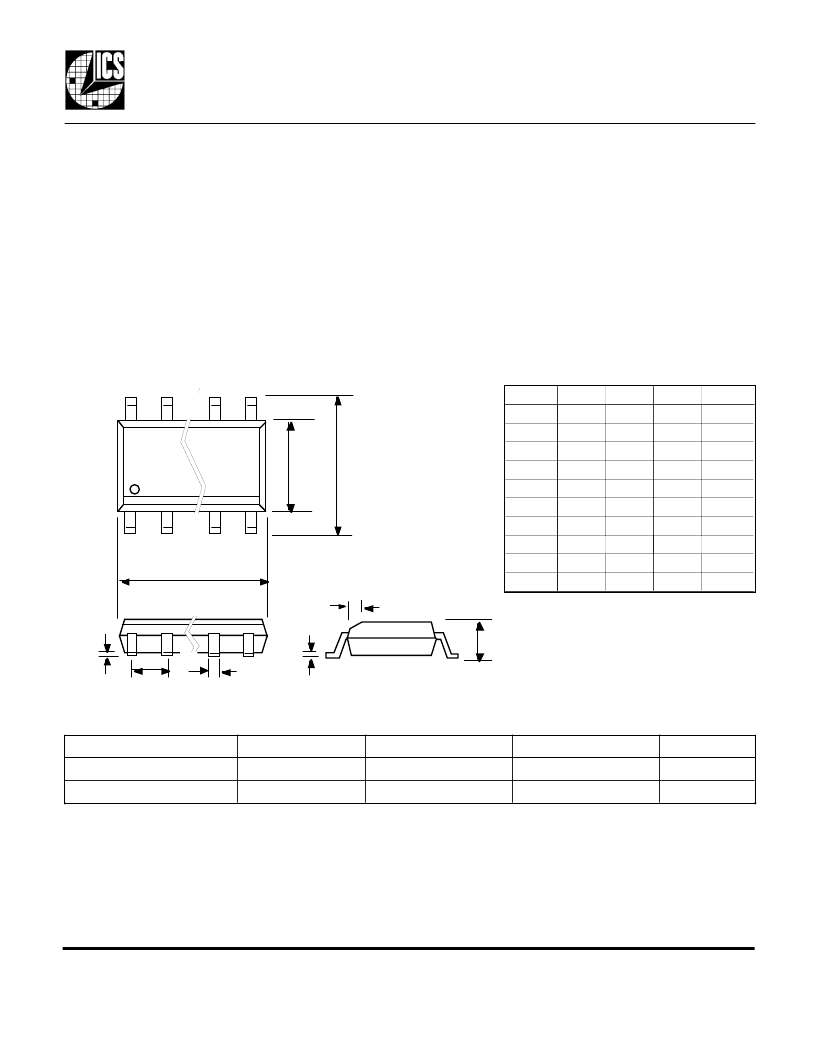
Package Outline and Package Dimensions
Ordering Information
Part/Order Number
ICS614M-01
ICS614M-01T
Marking
ICS614M-01
ICS614M-01
Shipping packaging
tubes
tape and reel
Package
Temperature
0 to 70 C
0 to 70 C
16 pin narrow SOIC
16 pin narrow SOIC
External Components/Crystal Selection
The ICS614-01 requires a minimum number of external components for proper operation. Decoupling
capacitors of 0.01 μF should be connected between VDD and GND, one between pins 4 and 5, and one
between pins 13 and 12, as close to the part as possible. A series termination resistor of 33
may be used
for each clock output. The 27.000 MHz crystal must be connected as close to the chip as possible. The
crystal should be a fundamental mode, parallel resonant, 30 ppm or better. Do not use third overtone.
Crystal capacitors should be connected from pins X1 to ground and X2 to ground. In general, the value of
these capacitors is given by the following equation, where C
L
is the crystal load capacitance: Crystal caps
(pF) = (C
L
-6) x 2. So for a crystal with 16 pF load capacitance, two 20 pF caps can be used. For any given
board layout, ICS can measure the board capacitance and recommend the exact capacitance value to use.
b
D
E
H
e
Q
c
h x 45°
A
Rev. 12308, version A . First publication, Preliminary.
Rev. 2019, version B. Added jitter, IDD specifications, showed VDDIO on pin 13, added i752 designation.
16 pin SOIC narrow
Inches
Min
0.055
0.013
0.007
0.385
0.150
0.225
Millimeters
Min
1.397
0.330
0.191
9.779
3.810
5.715
1.27 BSC
0.016
0.01
0.102
Symbol
A
b
c
D
E
H
e .050 BSC
h
Q
Max
0.070
0.019
0.010
0.400
0.160
0.245
Max
1.778
0.483
0.254
10.160
4.064
6.223
0.406
0.254
0.004
相關(guān)PDF資料 |
PDF描述 |
|---|---|
| ICS614-01 | 16 pin Intel Graphics Clock Source |
| ICS615 | Set-Top Box Clock Source |
| ICS615M | RES 41.2 OHM 1/10W 1% 0603 SMD |
| ICS615MT | Set-Top Box Clock Source |
| ICS620-01 | Digital Still Camera Clock Source |
相關(guān)代理商/技術(shù)參數(shù) |
參數(shù)描述 |
|---|---|
| ICS615 | 制造商:ICS 制造商全稱:ICS 功能描述:Set-Top Box Clock Source |
| ICS615M | 制造商:ICS 制造商全稱:ICS 功能描述:Set-Top Box Clock Source |
| ICS615MT | 制造商:ICS 制造商全稱:ICS 功能描述:Set-Top Box Clock Source |
| ICS620-01 | 制造商:ICS 制造商全稱:ICS 功能描述:Digital Still Camera Clock Source |
| ICS620-01R | 制造商:ICS 制造商全稱:ICS 功能描述:Digital Still Camera Clock Source |
發(fā)布緊急采購,3分鐘左右您將得到回復(fù)。