- 您現(xiàn)在的位置:買賣IC網(wǎng) > PDF目錄383083 > ICL8052CDD (INTERSIL CORP) Precision 4 1/2 Digit, A/D Converter PDF資料下載
參數(shù)資料
| 型號: | ICL8052CDD |
| 廠商: | INTERSIL CORP |
| 元件分類: | ADC |
| 英文描述: | Precision 4 1/2 Digit, A/D Converter |
| 中文描述: | 1-CH 4-BIT DUAL-SLOPE ADC, PARALLEL ACCESS, CDIP14 |
| 封裝: | CERDIP-14 |
| 文件頁數(shù): | 5/21頁 |
| 文件大小: | 198K |
| 代理商: | ICL8052CDD |
5-10
Absolute Maximum Ratings
Thermal Information
ICL8052, ICL8068
Supply Voltage . . . . . . . . . . . . . . . . . . . . . . . . . . . . . . . . . . . . .
±
18V
Differential Input Voltage
(8068) . . . . . . . . . . . . . . . . . . . . . . . . . . . . . . . . . . . . . . . . . .
±
30V
(8052) . . . . . . . . . . . . . . . . . . . . . . . . . . . . . . . . . . . . . . . . . . .
±
6V
Input Voltage (Note 2). . . . . . . . . . . . . . . . . . . . . . . . . . . . . . . .
±
15V
Output Short Circuit Duration All Outputs (Note 3). . . . . . . Indefinite
ICL7104
V+ Supply (GND to V+) . . . . . . . . . . . . . . . . . . . . . . . . . . . . . . . 12V
V++ to V-. . . . . . . . . . . . . . . . . . . . . . . . . . . . . . . . . . . . . . . . . . . 32V
Positive Supply Voltage (GND to V++) . . . . . . . . . . . . . . . . . . . . 17V
Negative Supply Voltage (GND to V-). . . . . . . . . . . . . . . . . . . . .-17V
Analog Input Voltage (Pins 32 - 39)(Note 4). . . . . . . . . . . . V++ to V-
Digital Input Voltage
(Pins 2 - 30) (Note 5) . . . . . . . . . . . . (GND - 0.3V) to (V+ + 0.3V)
Operating Conditions
Temperature Range . . . . . . . . . . . . . . . . . . . . . . . . . . . .0
o
C to 70
o
C
Thermal Resistance (Typical, Note 1)
14 Ld PDIP Package . . . . . . . . . . . . . .
40 Ld PDIP Package . . . . . . . . . . . . . .
14 Ld CERDIP Package . . . . . . . . . . .
Maximum Junction Temperature (Ceramic Package). . . . . . . . . 175
o
C
Maximum Junction Temperature (Plastic Package) . . . . . . . . 150
o
C
Maximum Storage Temperature Range . . . . . . . . . .-65
o
C to 150
o
C
Maximum Lead Temperature (Soldering, 10s) . . . . . . . . . . . . 300
o
C
θ
JA
(
o
C/W)
100
60
75
θ
JC
(
o
C/W)
N/A
N/A
20
CAUTION: Stresses above those listed in “Absolute Maximum Ratings” may cause permanent damage to the device. This is a stress only rating and operation
of the device at these or any other conditions above those indicated in the operational sections of this specification is not implied.
NOTES:
1.
θ
JA
is measured with the component mounted on an evaluation PC board in free air.
2. For supply voltages less than
±
15V, the absolute maximum input voltage is equal to the supply voltage.
3. Short circuit may be to ground or either supply. Rating applies to 70
o
C ambient temperature.
4. Input voltages may exceed the supply voltages provided the input current is limited to
±
100
μ
A.
5. Connecting any digital inputs or outputs to voltages greater than V+ or less than GND may cause destructive device latchup. For this
reason it is recommended that the power supply to the ICL7104 be established before any inputs from sources not on that supply are
applied.
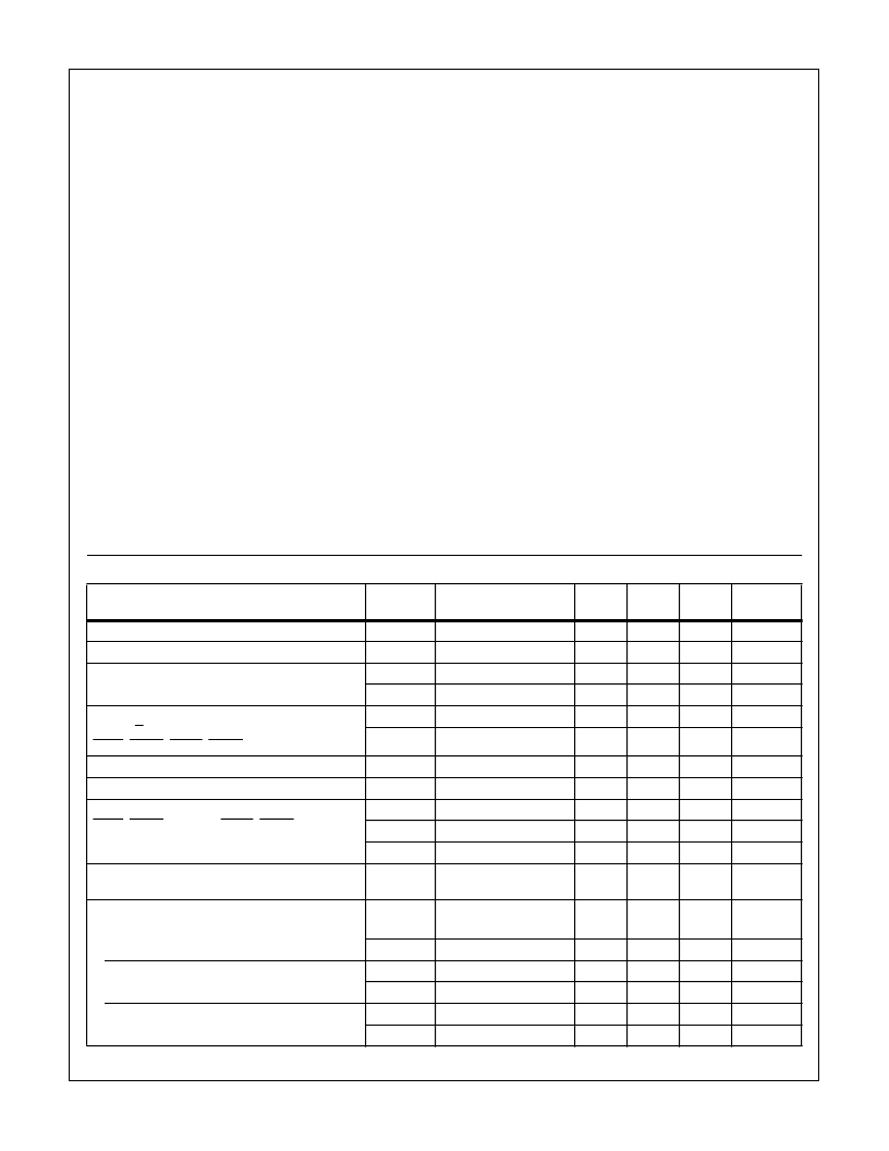
ICL7104 Electrical Specifications
V+ = +5V, V++ = +15V, V- = -15V, T
A
= 25
o
C, f
CLOCK
= 200kHz
PARAMETER
SYMBOL
TEST
CONDITIONS
MIN
TYP
MAX
UNITS
Clock Input, CLK 1
I
IN
I
IN
I
IH
I
IL
I
IH
I
IL
V
IN
= +5V to 0V
V
IN
= 0V to +5V
V
IN
= +5V
V
IN
= 0V
V
IN
= +5V
V
IN
= 0V
±
2
±
7
±
30
μ
A
Comparator I/P, COMP IN (Note 6)
-10
±
0.001
10
μ
A
Inputs with Pulldown, MODE
1
5
30
μ
A
-10
±
0.01
10
μ
A
Inputs with Pullups
SEN, R/H
LBEN, MBEN, HBEN, CE/LD (Note 7)
-10
±
0.01
10
μ
A
-30
-5
-1
μ
A
Input High Voltage, All Digital Inputs
V
IH
V
IL
V
OL
V
OH
V
OH
I
OL
2.5
2.0
-
V
Input Low Voltage, All Digital Inputs
-
1.5
1.0
V
Digital Outputs Three-Stated On,
LBEN, MBEN (16 Only), HBEN, CE/LD
BIT n, POL, OR (Note 8)
I
OL
= 1.6mA
I
OH
= -10
μ
A
I
OH
= -240
μ
A
0
≤
V
OUT
≤
V+
-
0.27
0.4
V
-
4.5
-
V
2.4
3.5
-
V
Digital Outputs Three-Stated Off
Bit n, POL, OR
-10
±
0.001
+10
μ
A
Non Three-State Digital Output
STTS
V
OL
V
OH
V
OL
V
OH
V
OL
V
OH
I
OL
= 3.2mA
I
OH
= -400
μ
A
I
OL
= 320
μ
A
I
OH
= -320
μ
A
I
OL
= 1.6mA
I
OH
= -320
μ
A
-
0.3
0.4
V
2.4
3.3
-
V
Clock 2
-
0.5
-
V
-
4.5
-
V
Clock 3 (-14 Only)
-
0.27
0.4
V
2.4
3.5
-
V
ICL8052/ICL7104, ICL8068/ICL7104
相關PDF資料 |
PDF描述 |
|---|---|
| ICL8052CPD | 14-Bit/16-Bit, Microprocessor- Compatible, 2-Chip, A/D Converter |
| ICL7104-16 | 16-Bit, Microprocessor-Compatible, 2-Chip, A/D Converter(16位、微處理器兼容的2片ADC) |
| ICL7104 | 14-Bit/16-Bit, Microprocessor- Compatible, 2-Chip, A/D Converter |
| ICL7104-14CPL | 14-Bit/16-Bit, Microprocessor- Compatible, 2-Chip, A/D Converter |
| ICL7104-16CPL | 14-Bit/16-Bit, Microprocessor- Compatible, 2-Chip, A/D Converter |
相關代理商/技術參數(shù) |
參數(shù)描述 |
|---|---|
| ICL8052CDL | 制造商:未知廠家 制造商全稱:未知廠家 功能描述:Converter IC |
| ICL8052CJD | 制造商:Rochester Electronics LLC 功能描述:- Bulk |
| ICL8052CPD | 制造商:Rochester Electronics LLC 功能描述:- Bulk |
| ICL8052CPL | 制造商:未知廠家 制造商全稱:未知廠家 功能描述:Converter IC |
| ICL8053 | 制造商:INTERSIL 制造商全稱:Intersil Corporation 功能描述:Precision Chip Pairs for A/D Conversion |
發(fā)布緊急采購,3分鐘左右您將得到回復。