- 您現(xiàn)在的位置:買賣IC網(wǎng) > PDF目錄383083 > ICL3310EIA-T (INTERSIL CORP) BLADE SCALPEL #23 2PC PDF資料下載
參數(shù)資料
| 型號(hào): | ICL3310EIA-T |
| 廠商: | INTERSIL CORP |
| 元件分類: | 通用總線功能 |
| 英文描述: | BLADE SCALPEL #23 2PC |
| 中文描述: | DUAL LINE TRANSCEIVER, PDSO20 |
| 封裝: | PLASTIC, MO-150-AE, SSOP-20 |
| 文件頁數(shù): | 6/10頁 |
| 文件大小: | 351K |
| 代理商: | ICL3310EIA-T |
6
Capacitor Selection
The charge pumps require 0.1
μ
F or greater capacitors for
operation with 3.3V
≤
V
CC
≤
5.5V. Increasing the capacitor
values (by a factor of 2) reduces ripple on the transmitter
outputs and slightly reduces power consumption. C
2
, C
3
,
and C
4
can be increased without increasing C
1
’s value,
however, do not increase C
1
without also increasing C
2
, C
3
,
and C
4
to maintain the proper ratios (C
1
to the other
capacitors).
When using minimum required capacitor values, make sure
that capacitor values do not degrade excessively with
temperature. If in doubt, use capacitors with a larger nominal
value. The capacitor’s equivalent series resistance (ESR)
usually rises at low temperatures and it influences the
amount of ripple on V+ and V-.
Operation Down to 2.7V
ISL3310E transmitter outputs meet RS-562 levels (
±
3.7V), at
the full data rate, with V
CC
as low as 2.7V. RS-562 levels
typically ensure interoperability with RS-232 devices.
Power Supply Decoupling
In most circumstances a 0.1
μ
F bypass capacitor is
adequate. In applications that are particularly sensitive to
power supply noise, decouple V
CC
to ground with a
capacitor of the same value as the charge-pump capacitor C
1
.
Connect the bypass capacitor as close as possible to the IC.
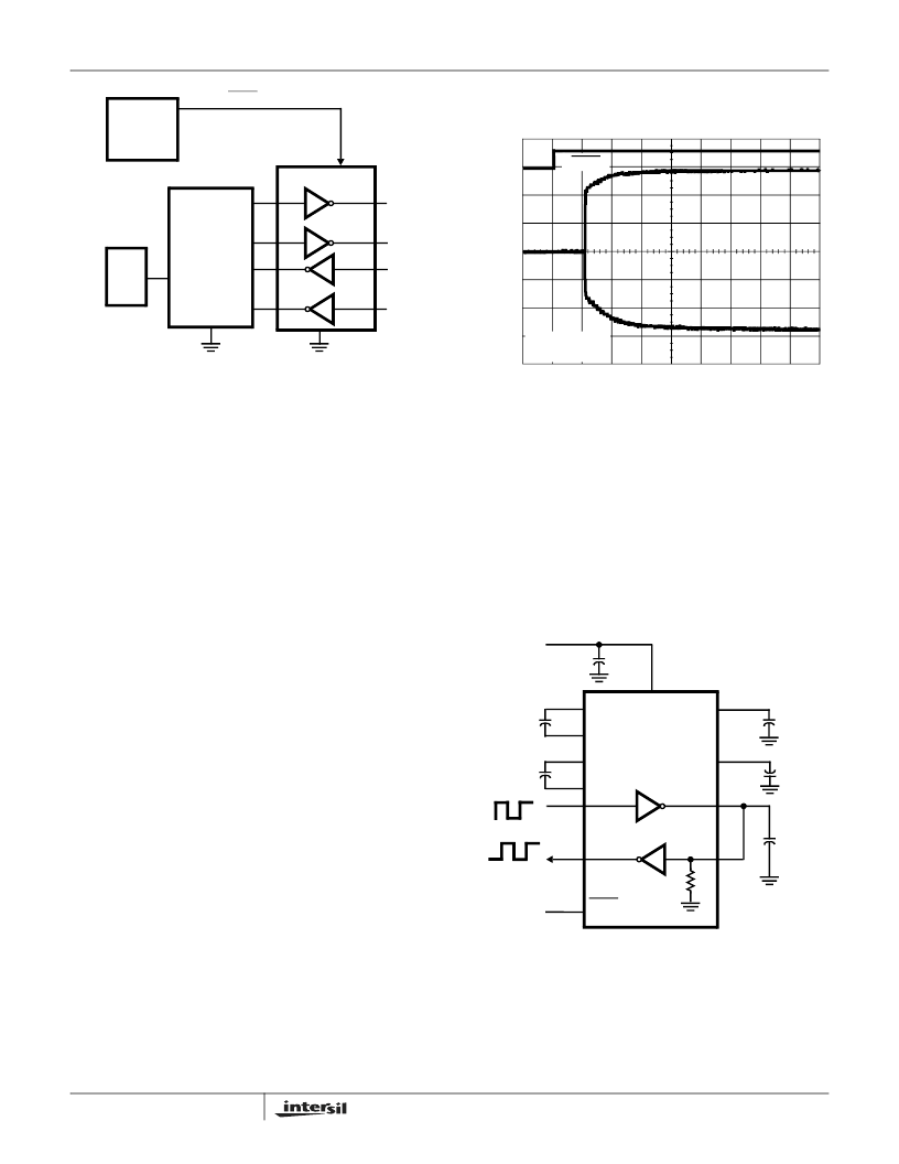
Transmitter Outputs when Exiting
Powerdown
Figure 5 shows the response of two transmitter outputs
when exiting powerdown mode. As they activate, the two
transmitter outputs properly go to opposite RS-232 levels,
with no glitching, ringing, nor undesirable transients. Each
transmitter is loaded with 3k
in parallel with 2500pF. Note
that the transmitters enable only when the magnitude of the
supplies exceed approximately 3V.
High Data Rates
The ICL3310E maintains the RS-232
±
5V minimum
transmitter output voltages even at high data rates. Figure 6
details a transmitter loopback test circuit, and Figure 7
illustrates the loopback test result at 120kbps. For this test,
all transmitters were simultaneously driving RS-232 loads in
parallel with 1000pF, at 120kbps. Figure 8 shows the
loopback results for a single transmitter driving 1000pF and
an RS-232 load at 250kbps. The static transmitter was also
loaded with an RS-232 receiver.
FIGURE 4. CONNECTIONS FOR MANUAL POWERDOWN
PWR
MGT
LOGIC
SHDN
CPU
I/O
ICL3310E
UART
FIGURE 6. TRANSMITTER LOOPBACK TEST CIRCUIT
TIME (20μs/DIV)
T1
T2
2V/DIV
5V/DIV
V
CC
= +3.3V
C1 - C4 = 0.1μF
SHDN
FIGURE 5. TRANSMITTER OUTPUTS WHEN EXITING
POWERDOWN
ICL3310E
V
CC
C
1
C
2
C
4
+
C
3
+
+
+
1000pF
V+
V-
5K
T
IN
R
OUT
C1+
C1-
C2+
C2-
R
IN
T
OUT
+
V
CC
0.1μF
V
CC
SHDN
ICL3310E
相關(guān)PDF資料 |
PDF描述 |
|---|---|
| ICL3310 | +3V to +5.5V, 1 Microamp, 250kbps, RS-232 Transmitter/Receiver |
| ICL3310CB | +3V to +5.5V, 1 Microamp, 250kbps, RS-232 Transmitter/Receiver |
| ICL3310CB-T | +3V to +5.5V, 1 Microamp, 250kbps, RS-232 Transmitter/Receiver |
| ICL3310IB | +3V to +5.5V, 1 Microamp, 250kbps, RS-232 Transmitter/Receiver |
| ICL3310IB-T | +3V to +5.5V, 1 Microamp, 250kbps, RS-232 Transmitter/Receiver |
相關(guān)代理商/技術(shù)參數(shù) |
參數(shù)描述 |
|---|---|
| ICL3310EIB | 制造商:Rochester Electronics LLC 功能描述:- Bulk |
| ICL3310EIB-T | 制造商:INTERSIL 制造商全稱:Intersil Corporation 功能描述:+/- 15kV ESD Protected, +3V to +5.5V, 1 Microamp, 250kbps, RS-232 Transmitter/Receiver |
| ICL3310IB | 制造商:Rochester Electronics LLC 功能描述:RS232 3V 2D/2R SHUTDOWN 18SOIC IND - Bulk 制造商:Intersil Corporation 功能描述: |
| ICL3310IB-T | 制造商:Rochester Electronics LLC 功能描述:RS232 3V 2D/2R SHUTDOWN 18SOIC IND (TAPE&REEL) - Tape and Reel 制造商:Intersil Corporation 功能描述: |
| ICL351-LS | 制造商:ICE 制造商全稱:ice Components, Ins. 功能描述:3-phase VRD/POL Inductor |
發(fā)布緊急采購,3分鐘左右您將得到回復(fù)。