- 您現在的位置:買賣IC網 > PDF目錄383077 > ICE2AS01 (INFINEON TECHNOLOGIES AG) PWM-FF IC PDF資料下載
參數資料
| 型號: | ICE2AS01 |
| 廠商: | INFINEON TECHNOLOGIES AG |
| 英文描述: | PWM-FF IC |
| 中文描述: | 脈寬調制集成電路法郎 |
| 文件頁數: | 11/24頁 |
| 文件大小: | 1291K |
| 代理商: | ICE2AS01 |
Version 2.0 11 1 Feb 2002
ICE2AS01/G
ICE2BS01/G
Functional Description
recovery time. To avoid a premature termination of the
switching pulse this spike is blanked out with a time
constant of t
= 220ns. During that time the output of
the Current-Limit Comparator cannot switch off the
gate drive.
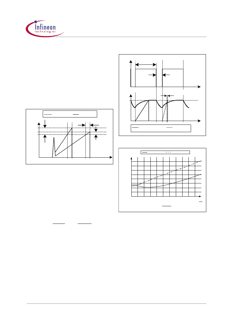
3.5.2
Propagation Delay Compensation
In case of overcurrent detection the shut down of the
external Power Switch is delayed due to the
propagation delay of the circuit. This delay causes an
overshoot of the peak current I
which depends on
the ratio of dI/dt of the peak current (see Figure 14).
.
Figure 14
Current Limiting
The overshoot of Signal2 is bigger than of Signal1 due
to the steeper rising waveform.
A propagation delay compensation is integrated to
bound the overshoot dependent on dI/dt of the rising
primary current. That means the propagation delay
time between exceeding the current sense threshold
V
csth
and the switch off of the external Power Switch is
compensated over temperature within a range of at
least
.
dI
R
Sense
0
×
≤
So current limiting is now capable in a very accurate
way (see Figure 16).
E.g. I
= 0.5A with R
= 2 . Without propagation
delay compensation the current sense threshold is set
to a static voltage level V
=1V. A current ramp of
dI/dt = 0.4A/μs, that means dV
/dt = 0.8V/μs, and a
propagation delay time of i.e. t
=180ns
leads then to an I
peak
overshoot of 12%. By means of
propagation delay compensation the overshoot is only
about 2% (see Figure 15).
The propagation delay compensation is done by
means of a dynamic threshold voltage V
csth
(see Figure
15). In case of a steeper slope the switch off of the
driver is earlier to compensate the delay.
Figure 15
Dynamic Voltage Threshold V
csth
Figure 16
Overcurrent Shutdown
3.6
PWM-Latch
The oscillator clock output applies a set pulse to the
PWM-Latch when initiating the external Power Switch
conduction. After setting the PWM-Latch can be reset
by the PWM-OP, the Soft-Start-Comparator, the
Current-Limit-Comparator, Comparator C3 or the
Error-Latch of the Protection Unit. In case of reseting
the driver is shut down immediately.
3.7
Driver
The driver is a fast totem pole gate drive, which is
designed to avoid cross conduction currents and which
is equipped with a Zener diode Z1 (see Figure 17) in
order to improve the control of the gate attached power
t
I
Sense
I
Limit
t
Propagation Delay
I
Overshoot1
I
peak1
Signal1
Signal2
I
Overshoot2
I
peak2
dt
dV
dt
Sense
peak
1
≤
t
V
csth
V
OSC
Signal1
Signal2
V
Sense
Propagation Delay
max. Duty Cycle
off time
t
0,9
0,95
1
1,05
1,1
1,15
1,2
1,25
1,3
0
0,2
0,4
0,6
0,8
1
dV
Sense
1,2
1,4
1,6
1,8
2
with compensation
without compensation
dt
s
V
μ
S
V
V
相關PDF資料 |
PDF描述 |
|---|---|
| ICE2AS01G | PWM-FF IC |
| ICE2BS01 | PWM-FF IC |
| ICE2BS01G | PWM-FF IC |
| ICE3A1065L | Off-Line SMPS Current Mode Controller with integrated 650V Startup Cell/Depletion CoolMOS⑩ and Latched off Mode |
| ICE3B0365L | Off-Line SMPS Current Mode Controller with integrated 650V Startup Cell/Depletion CoolMOS⑩ and Latched off Mode |
相關代理商/技術參數 |
參數描述 |
|---|---|
| ICE2AS01_06 | 制造商:INFINEON 制造商全稱:Infineon Technologies AG 功能描述:Off-Line SMPS Current Mode Controller |
| ICE2AS01G | 功能描述:初級與次級側 PWM 控制器 SMPS ICS RoHS:否 制造商:ON Semiconductor 輸出端數量:1 開關頻率:250 KHz 工作電源電壓:- 0.3 V to + 28 V 最大工作溫度:+ 85 C 最小工作溫度:- 5 C 封裝 / 箱體:SOIC-8 Narrow 封裝:Reel |
| ICE2AS01GHUMA1 | 制造商:Infineon Technologies AG 功能描述:ELECTRONIC INTEGRATED CIRCUITS - Tape and Reel |
| ICE2AS01GNT | 制造商:Infineon Technologies AG 功能描述:Current Mode PWM Controller 8-Pin DSO |
| ICE2AS01GXT | 功能描述:初級與次級側 PWM 控制器 CTRLR SMP SUPPLIES LOW POWER PFC 27V RoHS:否 制造商:ON Semiconductor 輸出端數量:1 開關頻率:250 KHz 工作電源電壓:- 0.3 V to + 28 V 最大工作溫度:+ 85 C 最小工作溫度:- 5 C 封裝 / 箱體:SOIC-8 Narrow 封裝:Reel |
發(fā)布緊急采購,3分鐘左右您將得到回復。