- 您現(xiàn)在的位置:買賣IC網(wǎng) > PDF目錄371897 > HSP45256 (Intersil Corporation) Binary Correlator PDF資料下載
參數(shù)資料
| 型號(hào): | HSP45256 |
| 廠商: | Intersil Corporation |
| 英文描述: | Binary Correlator |
| 中文描述: | 二元相關(guān)器 |
| 文件頁(yè)數(shù): | 20/23頁(yè) |
| 文件大小: | 154K |
| 代理商: | HSP45256 |
第1頁(yè)第2頁(yè)第3頁(yè)第4頁(yè)第5頁(yè)第6頁(yè)第7頁(yè)第8頁(yè)第9頁(yè)第10頁(yè)第11頁(yè)第12頁(yè)第13頁(yè)第14頁(yè)第15頁(yè)第16頁(yè)第17頁(yè)第18頁(yè)第19頁(yè)當(dāng)前第20頁(yè)第21頁(yè)第22頁(yè)第23頁(yè)

20
Reloading Data During Operation
RLOAD and CLOAD are asynchronous signals that are
designed to be driven by the memory interface signals of a
microprocessor. TXFR is synchronized to CLK so that the
mask or reference data is updated on a specific clock cycle.
In the normal mode of operation, the user loads the
reference and mask memories, then pulses TXFR to use
that data. The correlator uses the new mask or reference
information immediately. Loading of the reference and mask
data remains asynchronous as long as there is at least one
cycle of CLK between the rising edge of RLOAD or CLOAD
and the TXFR pulse.
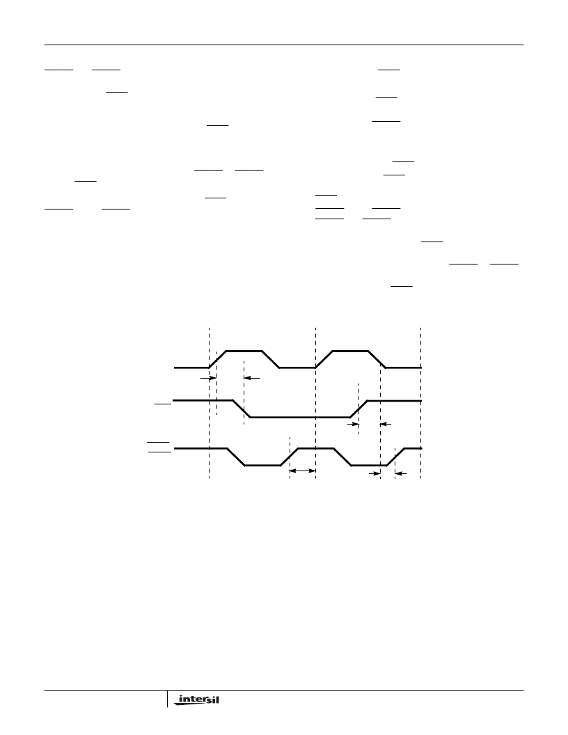
If the system timing makes it necessary for TXFR and
RLOAD and/or CLOAD to be active during the same clock
cycle, then they must be treated as synchronous signals; the
timing for this case is shown in Figure 24 and given in the AC
Timing Specifications (t
THCL
and t
CLLH
). In this example,
data is loaded during clock cycle 1 and transferred on the
rising edge of CLK that occurs in clock cycle two. Another
set of data is loaded during clock cycle 2, which will be
transferred by a later TXFR pulse. The sequence of events is
as follows:
1. In clock cycle 1, TXFR becomes active at least t
TH
nano-
seconds after the rising edge of CLK.
2. RLOAD and/or CLOAD pulses low; the timing is not
critical as long as its rising edge occurs before the end of
clock cycle 1. If this condition is not met, it is undeter-
mined whether the data loaded by this pulse will be trans-
ferred by the current TXFR pulse.
3. The rising edge of TXFR occurs while CLK is high during
clock cycle 2. The margin between the rising edge of
TXFR and the falling edge of CLK is defined by t
THCL
.
4. RLOAD and/or CLOAD pulses low. The rising edge of
RLOAD and CLOAD must occur after the falling edge of
CLK. The margin between the two is defined by t
CLLH
.
The time from the rising edge of TXFR to the falling edge of
CLK must be greater than t
THCL
, and the time from the
falling edge of CLK to the rising edge of RLOAD or CLOAD
must be greater than t
s
. If this timing is violated, the data
being transferred by the TXFR pulse shown may or may not
include the data loaded in clock cycle 2.
CLK
TXFR
RLOAD,
CLOAD
CLOCK CYCLE 1
CLOCK CYCLE 2
FIGURE 24. LOADING AND TRANSFERRING DATA DURING THE SAME CLOCK CYCLE
t
TH
1.
2.
t
THCL
3.
t
CLLH
4.
HSP45256
相關(guān)PDF資料 |
PDF描述 |
|---|---|
| HSP45256883 | Binary Correlator |
| HSP45256JC-25 | Binary Correlator |
| HSP45256JC-33 | Binary Correlator |
| HSP48410GC-33 | Histogrammer/Accumulating Buffer |
| HSP48410GC-40 | Histogrammer/Accumulating Buffer |
相關(guān)代理商/技術(shù)參數(shù) |
參數(shù)描述 |
|---|---|
| HSP45256 WAF | 制造商:Intersil Corporation 功能描述: |
| HSP45256/883 | 制造商:INTERSIL 制造商全稱:Intersil Corporation 功能描述:Binary Correlator |
| HSP45256883 | 制造商:INTERSIL 制造商全稱:Intersil Corporation 功能描述:Binary Correlator |
| HSP45256GC-25 | 制造商:INTERSIL 制造商全稱:Intersil Corporation 功能描述:Binary Correlator |
| HSP45256GC-33 | 制造商:Rochester Electronics LLC 功能描述:- Bulk 制造商:Harris Corporation 功能描述: |
發(fā)布緊急采購(gòu),3分鐘左右您將得到回復(fù)。