- 您現(xiàn)在的位置:買賣IC網(wǎng) > PDF目錄1923 > HSP43220JC-33Z (Intersil)IC DECIMATING DGTL FILTER 84PLCC PDF資料下載
參數(shù)資料
| 型號(hào): | HSP43220JC-33Z |
| 廠商: | Intersil |
| 文件頁(yè)數(shù): | 18/21頁(yè) |
| 文件大小: | 0K |
| 描述: | IC DECIMATING DGTL FILTER 84PLCC |
| 標(biāo)準(zhǔn)包裝: | 15 |
| 濾波器類型: | 數(shù)字 |
| 濾波器數(shù): | 4 |
| 電源電壓: | 4.75 V ~ 5.25 V |
| 安裝類型: | 表面貼裝 |
| 封裝/外殼: | 84-LCC(J 形引線) |
| 供應(yīng)商設(shè)備封裝: | 84-PLCC(29.21x29.21) |
| 包裝: | 管件 |
第1頁(yè)第2頁(yè)第3頁(yè)第4頁(yè)第5頁(yè)第6頁(yè)第7頁(yè)第8頁(yè)第9頁(yè)第10頁(yè)第11頁(yè)第12頁(yè)第13頁(yè)第14頁(yè)第15頁(yè)第16頁(yè)第17頁(yè)當(dāng)前第18頁(yè)第19頁(yè)第20頁(yè)第21頁(yè)

6
FN2486.10
October 10, 2008
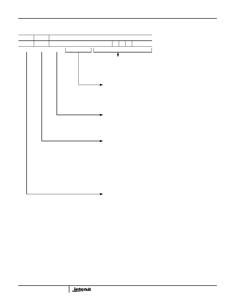
DDF Control Registers
F_Register (A1 = 0, A0 = 0)
FIGURE 4.
F_OAD
F_BYP
F_ESYM
F_DRATE
F_TAPS
FA0
FB0
ES0
D3
D2
D1
D0
T8T7
T6
T5
T4
T3T2T1T0
F_TAPS
Bits T0-T8 are used to specify the number of FIR filter taps. The number
entered is one less than the number of taps required. For example, to
specify a 511 tap filter F_TAPS would be programmed to 510. The
minimum number of FIR taps = 3 (F_TAPS = 2).
F_DRATE
Bits D0-D3 are used to specify the amount of FIR decimation. The
number entered is one less than the decimation required. For example,
to specify decimation of 16, F_DRATE would be programmed to 15. For
no FIR decimation, F_DRATE would be set equal to 0. FDRATE +1 is
defined as FDEC.
F_ESYM
Bit ES0 is used to select the FIR symmetry. F_ESYM is set equal to one
to select even symmetry and set equal to zero to select odd symmetry.
When F_ESYM is one, data is added in the pre-adder; when it is zero,
data is subtracted. Normally set to one.
F_BYP
FB0 is used to select FIR bypass mode. FIR bypass mode is selected by
setting F_BYP = 1. When FIR bypass mode is selected, the FIR is
internally set up for a 3 tap even symmetric filter, no decimation
(F_DRATE = 0) and F_OAD is set equal to one to zero one side of the
preadder. In FIR bypass mode all FIR filter parameters, except F_CLA,
are ignored, including the contents of the FIR coefficient RAM. In FIR
bypass mode the output data is brought output on the lower 16 bits of the
output bus DATA_OUT 0-15. To disable FIR bypass mode, F_BYP is set
equal to zero. When F_BYP is returned to zero, the coefficients must be
reloaded.
F_OAD
Bit FA0 is used to select the zero the preadder mode. This mode zeros
one of the inputs to the pre-adder. Zero preadder mode is selected by
setting F_OAD equal to one. This feature is useful when implementing
arbitrary phase filters or can be used to verify the filter coefficients. To
disable the Zero Preadder mode F_OAD is set equal to zero.
15
14
13
12
11
10
9
8
7
6
5
4
3
2
1
0
HSP43220
相關(guān)PDF資料 |
PDF描述 |
|---|---|
| IA188EM-PTQ100I-R-03 | IC MCU 8/16BIT 40MHZ 100TQFP |
| IA188ES-PTQ100I-R-03 | IC MCU 8/16BIT 40MHZ 100TQFP |
| IA6805E2PLC44IR0 | IC MCU 8BIT 5MHZ 44PLCC |
| IA82050-PDW28I-R-01 | IC ASYNCHRONOUS SERIAL CTRL |
| IA82510-PDW28I-R-01 | IC ASYNCHRONOUS SERIAL CTRL |
相關(guān)代理商/技術(shù)參數(shù) |
參數(shù)描述 |
|---|---|
| HSP43220TM-15 | 制造商:未知廠家 制造商全稱:未知廠家 功能描述:Digital Filter |
| HSP43220TM-25 | 制造商:未知廠家 制造商全稱:未知廠家 功能描述:Digital Filter |
| HSP43220VC-25 | 制造商:Rochester Electronics LLC 功能描述:- Bulk 制造商:Harris Corporation 功能描述: |
| HSP43220VC-33 | 制造商:Rochester Electronics LLC 功能描述:- Bulk |
| HSP43481 | 制造商:INTERSIL 制造商全稱:Intersil Corporation 功能描述:Digital Filter |
發(fā)布緊急采購(gòu),3分鐘左右您將得到回復(fù)。