- 您現(xiàn)在的位置:買賣IC網(wǎng) > PDF目錄353396 > HDSP-316Y-HG100 10 mm and 13 mm Slim Font Seven Segment Displays PDF資料下載
參數(shù)資料
| 型號: | HDSP-316Y-HG100 |
| 英文描述: | 10 mm and 13 mm Slim Font Seven Segment Displays |
| 中文描述: | 10毫米和13毫米超薄字體七段顯示器 |
| 文件頁數(shù): | 9/10頁 |
| 文件大小: | 87K |
| 代理商: | HDSP-316Y-HG100 |
8
HER Low Current
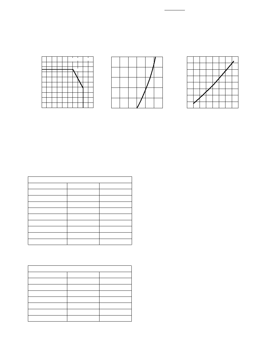
Figure 12. Relative Luminous
Intensity vs. DC Forward Current.
Figure 11. Forward Current vs.
Forward Voltage.
Figure 10. Maximum Allowable
Average or DC Current vs. Ambient
Temperature.
I F
–
FORWARD
CURRENT
PER
SEGMENT
–
mA
0
VF – FORWARD VOLTAGE – V
1.0
2.0
50
40
30
20
10
0.5
1.5
3.0
HER
2.5
16
0
2
4
6
8
10
12
14
20
100
90
80
70
60
50
40
30
TA – AMBIENT TEMPERATURE – °C
I F
AVE.
MAX
–
MAXIMUM
AVERAGE
FORWARD
CURRENT
PER
SEGMENT
–
mA
120
110
20
18
J-A
R
θ
= 770°C/W
HER
RELATIVE
LUMINOUS
INTENSITY
(NORMALIZED
TO
1
AT
2
mA
FOR
HER
AND
TO
1
AT
4
mA
FOR
YELLOW
AND
GREEN
0
VF – FORWARD CURRENT PER SEGMENT – mA
610
16
12
10
6
2
28
16
HER
14
8
4
412
Intensity Bin Limits (mcd)
HER Low Current, AlGaAs Red Low Current
HER Std. Current, Green Std. Current,
Yellow Std. Current
HDSP-31xL/H, HDSP-51xL/H
IV Bin Category
Min.
Max.
E
0.180
0.360
F
0.280
0.560
G
0.450
0.900
H
0.700
1.400
I
1.100
2.200
K
1.800
3.600
L
2.800
5.600
M
4.500
9.000
N
7.000
15.000
HDSP-31xE/G/Y, HDSP-51xE/G/Y
IV Bin Category
Min.
Max.
G
0.450
0.900
H
0.700
1.400
I
1.100
2.200
K
1.800
3.600
L
2.800
5.600
M
4.500
9.000
N
7.000
15.000
相關PDF資料 |
PDF描述 |
|---|---|
| HDSP-315Y-HG200 | 10 mm and 13 mm Slim Font Seven Segment Displays |
| HDSP-316Y-HG200 | 10 mm and 13 mm Slim Font Seven Segment Displays |
| HDSP-315Y-HG300 | 10 mm and 13 mm Slim Font Seven Segment Displays |
| HDSP-316Y-HG300 | 10 mm and 13 mm Slim Font Seven Segment Displays |
| HDSP-315Y-HG400 | 10 mm and 13 mm Slim Font Seven Segment Displays |
相關代理商/技術參數(shù) |
參數(shù)描述 |
|---|---|
| HDSP-331A | 功能描述:LED 顯示器和配件 Red 643nm 0.3in 7 Segment RoHS:否 制造商:Avago Technologies 顯示器類型:7 Segment 數(shù)位數(shù)量:2 字符大小:7.8 mm x 14.22 mm 照明顏色:Red 波長:628 nm 共用管腳:Common Anode 工作電壓:2.05 V 工作電流:20 mA 最大工作溫度:+ 85 C 最小工作溫度:- 35 C 封裝:Tube |
| HDSP-331E | 功能描述:LED 顯示器和配件 Red 625nm 0.3in 7 Segment RoHS:否 制造商:Avago Technologies 顯示器類型:7 Segment 數(shù)位數(shù)量:2 字符大小:7.8 mm x 14.22 mm 照明顏色:Red 波長:628 nm 共用管腳:Common Anode 工作電壓:2.05 V 工作電流:20 mA 最大工作溫度:+ 85 C 最小工作溫度:- 35 C 封裝:Tube |
| HDSP-331G | 功能描述:LED 顯示器和配件 Green 573nm 0.3in 7 Segment RoHS:否 制造商:Avago Technologies 顯示器類型:7 Segment 數(shù)位數(shù)量:2 字符大小:7.8 mm x 14.22 mm 照明顏色:Red 波長:628 nm 共用管腳:Common Anode 工作電壓:2.05 V 工作電流:20 mA 最大工作溫度:+ 85 C 最小工作溫度:- 35 C 封裝:Tube |
| HDSP-331Y | 功能描述:LED 顯示器和配件 Yellow 590nm 0.3in 7 Segment RoHS:否 制造商:Avago Technologies 顯示器類型:7 Segment 數(shù)位數(shù)量:2 字符大小:7.8 mm x 14.22 mm 照明顏色:Red 波長:628 nm 共用管腳:Common Anode 工作電壓:2.05 V 工作電流:20 mA 最大工作溫度:+ 85 C 最小工作溫度:- 35 C 封裝:Tube |
| HDSP-332E | 功能描述:LED 顯示器和配件 Red 625nm 0.3in 7 Segment RoHS:否 制造商:Avago Technologies 顯示器類型:7 Segment 數(shù)位數(shù)量:2 字符大小:7.8 mm x 14.22 mm 照明顏色:Red 波長:628 nm 共用管腳:Common Anode 工作電壓:2.05 V 工作電流:20 mA 最大工作溫度:+ 85 C 最小工作溫度:- 35 C 封裝:Tube |
發(fā)布緊急采購,3分鐘左右您將得到回復。