- 您現(xiàn)在的位置:買賣IC網(wǎng) > PDF目錄371773 > HC1062A Low Voltage Telephone Speech Transmission Circuit / High/Low Level Mute PDF資料下載
參數(shù)資料
| 型號: | HC1062A |
| 英文描述: | Low Voltage Telephone Speech Transmission Circuit / High/Low Level Mute |
| 中文描述: | 低壓輸電線路電話語音/高/低級別靜音 |
| 文件頁數(shù): | 2/6頁 |
| 文件大小: | 1066K |
| 代理商: | HC1062A |
Page 2 of 6
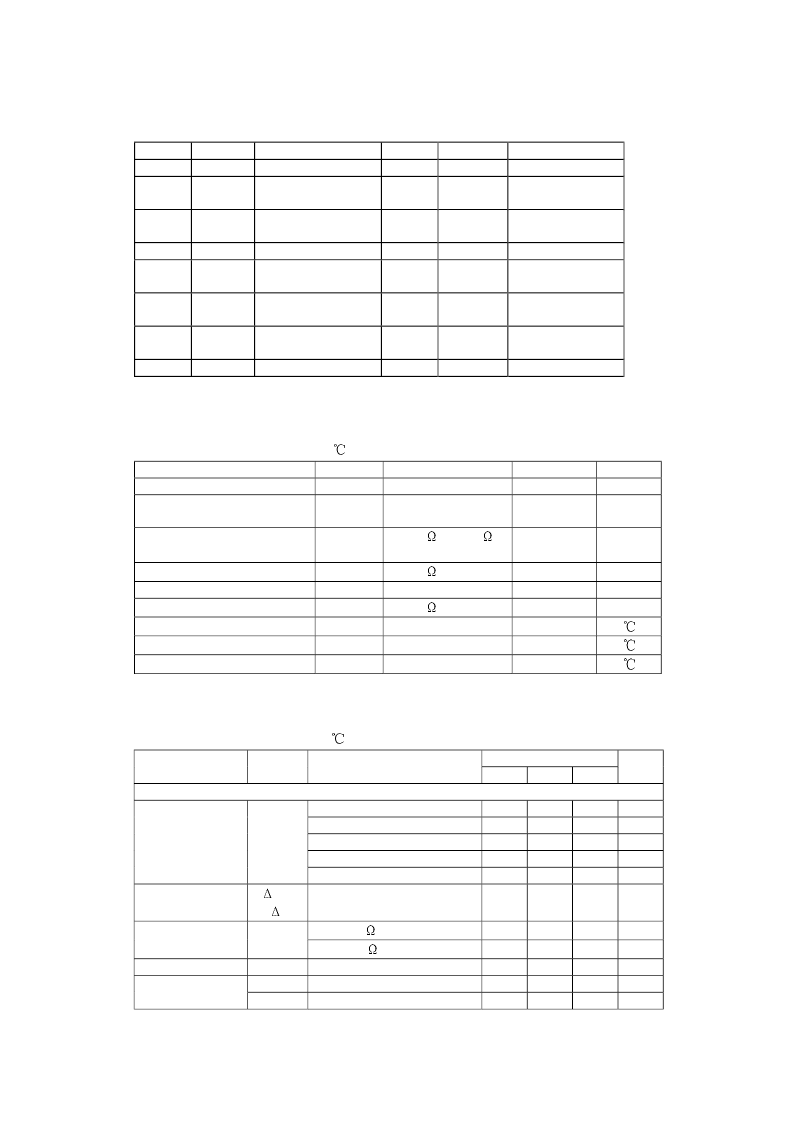
2. 2 Pin Description
Pin No.
1
Symbol
LN
+
Description
Positive Line
Gain Adjustment,
Transmitting AMP
Gain Adjustment,
Transmitting AMP
Receiving Output
Gain Adjustment,
Receiving AMP
Inverting
Microphone Input
Non-Inverting
Microphone Input
Current Stabilizer
Pin No.
9
Symbol
LN
-
Description
Negative Line
2
ADJ
MIC1
10
IN
R
Receiving Input
3
ADJ
MIC2
11
IN
DTMF
DTMF Input
4
OUT
R
12
IN
MUTR
Mute Input
5
ADJ
R
13
V
CC
Supply Voltage
6
IN
-
MIC
14
REG
De-coupling
7
IN
+
MIC
15
IN
AGC
AGC Input
8
CS
16
ADJ
SL
Slope Adjustment
3. Electrical Characteristics
3. 1 Absolute Maximum Ratings
Unless otherwise specified, T
amb
= 25
Parameter
Continuous Line Voltage
Symbol
V
LN
Conditions
During switch on
or interruption
R
9
=20
,R
10
=13
tp/p=1ms/5s
R
9
=20
R
9
=20
Value
12
Unit
V
Repetitive Line Voltage
V
LN
13.2
V
Repetitive Peak Line Voltage
V
LN
28
V
Line Current
Input Voltage of All Pins
Power Dissipation
Junction Temperature
Operating Temperature
Storage Temperature
I
LINS
V
PINS
P
D
T
J
T
amb
T
stg
140
mA
V
mW
V
CC
+0.7/-0.7
666
125
-25 ~ 75
-40 ~ 125
3. 2 Electrical Characteristics
Unless otherwise specified, T
amb
= 25
, I
LINE
=11~140mA, V
9
=0V, f=800H
Z
Value
Typ
Parameter
Symbol
Test Conditions
Min
Max
Unit
Supplies LN and V
CC
pin 1 and 13
I
LINE
=1mA
I
LINE
=4mA
I
LINE
=15mA
I
LINE
=100mA
I
LINE
=140mA
1.6
1.9
4.0
5.7
V
V
V
V
V
3.55
4.9
4.25
6.5
7.5
Line Voltage
When MIC Input
Open
V
LN
Variation with
Temperature
V
LN
with external
Resistor
Supply Current
Supply for
External Circuit
V
LN
T
/
I
LINE
=15mA
0.3
mV/K
R
AV
=68k
R
AV
=68k
V
CC
=2.8V
I
P
=1.2mA
I
P
=0mA
(LN to REG)
(REG to SLPE)
3.5
4.5
0.9
2.7
3.4
V
V
mA
V
V
V
LN
I
CC
V
CC
V
CC
1.35
2.2
相關(guān)PDF資料 |
PDF描述 |
|---|---|
| HC1198 | Peripheral IC |
| HC1199 | Peripheral IC |
| HC1200 | Peripheral IC |
| HC1247 | Peripheral IC |
| HC1279 | Peripheral IC |
相關(guān)代理商/技術(shù)參數(shù) |
參數(shù)描述 |
|---|---|
| HC106D | 制造商:HUASHAN 制造商全稱:HUASHAN 功能描述:Sensitive Gate Silicon Controlled Rectifier |
| HC-107 | 制造商:未知廠家 制造商全稱:未知廠家 功能描述:Hybrid Assemblies OPTIC RECEIVER MODULES |
| HC-10702 | 制造商:Distributed By MCM 功能描述:FLUORESCENT LAMP |
| HC-108 | 制造商:Thomas & Betts 功能描述: |
| HC109 | 制造商:SLS 制造商全稱:System Logic Semiconductor 功能描述:Dual J-K Flip-Flop with Set and Reset |
發(fā)布緊急采購,3分鐘左右您將得到回復(fù)。