- 您現(xiàn)在的位置:買賣IC網(wǎng) > PDF目錄370424 > HAL535SF-A (Electronic Theatre Controls, Inc.) Hall Effect Sensor IC PDF資料下載
參數(shù)資料
| 型號: | HAL535SF-A |
| 廠商: | Electronic Theatre Controls, Inc. |
| 英文描述: | Hall Effect Sensor IC |
| 中文描述: | 霍爾效應傳感器IC |
| 文件頁數(shù): | 4/21頁 |
| 文件大小: | 292K |
| 代理商: | HAL535SF-A |
HAL525, HAL535
4
Micronas
1.3. Marking Code
All Hall sensors have a marking on the package sur-
face (branded side). This marking includes the name
of the sensor and the temperature range.
1.4. Operating Junction Temperature Range
The Hall sensors from Micronas are specified to the
chip temperature (junction temperature T
J
).
A:
T
J
=
40
°
C to +170
°
C
K:
T
J
=
40
°
C to +140
°
C
E:
T
J
=
40
°
C to +100
°
C
The relationship between ambient temperature (T
A
)
and junction temperature is explained in Section 5.1.
on page 18.
1.5. Hall Sensor Package Codes
Hall sensors are available in a wide variety of packag-
ing versions and quantities. For more detailed informa-
tion, please refer to the brochure: “Ordering Codes for
Hall Sensors”.
1.6. Solderability
all packages: according to IEC68-2-58
During soldering reflow processing and manual
reworking, a component body temperature of 260
°
C
should not be exceeded.
Components stored in the original packaging should
provide a shelf life of at least 12 months, starting from
the date code printed on the labels, even in environ-
ments as extreme as 40
°
C and 90% relative humidity.
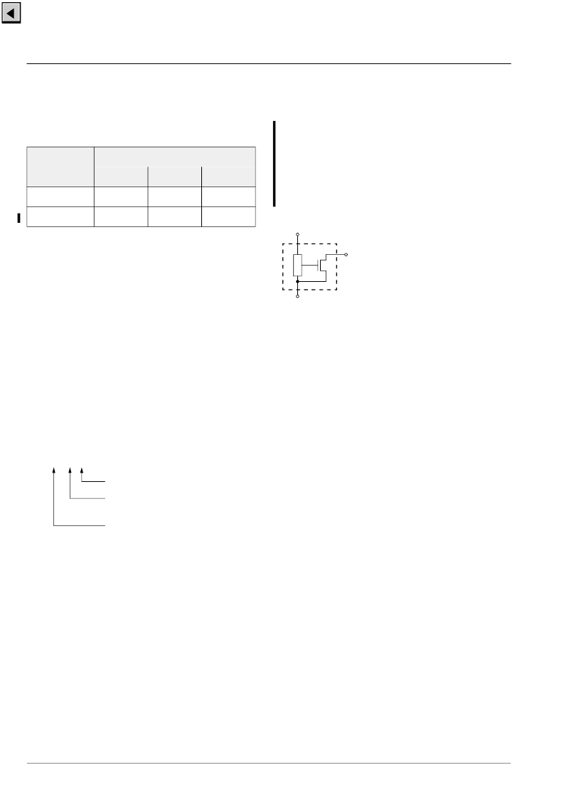
Fig. 1–1:
Pin configuration
Type
Temperature Range
A
K
E
HAL525
525A
525K
525E
HAL535
535A
535K
535E
HALXXXPA-T
Temperature Range: A, K, or E
Package: SF for SOT-89B
UA for TO-92UA
Type: 525 or 535
Example:
HAL525UA-E
→
Type: 525
→
Package: TO-92UA
→
Temperature Range: T
J
=
40
°
C to +100
°
C
1 V
DD
2
GND
3
OUT
相關PDF資料 |
PDF描述 |
|---|---|
| HAL535SF-E | Hall Effect Sensor IC |
| HAL535SF-K | Hall Effect Sensor IC |
| HAL535UA-A | Hall Effect Sensor IC |
| HAL535UA-E | Hall Effect Sensor IC |
| HAL535UA-K | Hall Effect Sensor IC |
相關代理商/技術參數(shù) |
參數(shù)描述 |
|---|---|
| HAL535SF-E | 制造商:未知廠家 制造商全稱:未知廠家 功能描述:Hall Effect Sensor IC |
| HAL535SF-K | 制造商:未知廠家 制造商全稱:未知廠家 功能描述:Hall Effect Sensor IC |
| HAL535UA-A | 制造商:未知廠家 制造商全稱:未知廠家 功能描述:Hall Effect Sensor IC |
| HAL535UA-E | 制造商:未知廠家 制造商全稱:未知廠家 功能描述:Hall Effect Sensor IC |
| HAL535UA-K | 制造商:未知廠家 制造商全稱:未知廠家 功能描述:Hall Effect Sensor IC |
發(fā)布緊急采購,3分鐘左右您將得到回復。