- 您現(xiàn)在的位置:買賣IC網(wǎng) > PDF目錄370420 > HA17901 (Hitachi,Ltd.) 500000 SYSTEM GATE 1.5 VOLT FPGA PDF資料下載
參數(shù)資料
| 型號(hào): | HA17901 |
| 廠商: | Hitachi,Ltd. |
| 元件分類: | FPGA |
| 英文描述: | 500000 SYSTEM GATE 1.5 VOLT FPGA |
| 中文描述: | 四重比較 |
| 文件頁數(shù): | 11/16頁 |
| 文件大小: | 79K |
| 代理商: | HA17901 |
HA17901, HA17339 Series
11
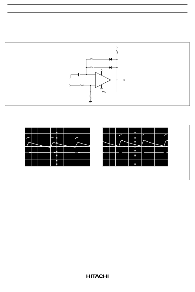
2. Pulse Generator
The charge and discharge circuits in the circuit from figure 1 are separated by diodes in this circuit. (See
figure 3.) This allows the pulse width and the duty cycle to be set independently. Figure 4 shows the
waveforms generated by this circuit.
–
+
HA17901
V
CC
V
CC
Vout
R
1
1M
D
1
IS2076
R
2
100k
V
CC
1M
1M
1M
C
80pF
D
2
IS2076
Figure 3 Pulse Generator
Horizontal: 5 V/div, Vertical: 20
μ
s/div, V
CC
= 15 V
Horizontal: 2 V/div, Vertical: 20
μ
s/div, V
CC
= 5 V
Figure 4 Operating Waveforms
3. Voltage Controlled Oscillator
In the circuit in figure 5, comparator A
1
operates as an integrator, A
2
operates as a comparator with
hysteresis, and A
3
operates as the switch that controls the oscillator frequency. If the output Vout1 is at
the low level, the A
3
output will go to the low level and the A1 inverting input will become a lower
level than the A1 noninverting input. The A1 output will integrate this state and its output will increase
towards the high level. When the output of the integrator A
1
exceeds the level on the comparator A
2
inverting input, A
2
inverts to the high level and both the output Vout1 and the A
3
output go to the high
level. This causes the integrator to integrate a negative state, resulting in its output decreasing towards
the low level. Then, when the A
1
output level becomes lower than the level on the A
2
noninverting
input, the output Vout1 is once again inverted to the low level. This operation generates a square wave
on Vout1 and a triangular wave on Vout2.
相關(guān)PDF資料 |
PDF描述 |
|---|---|
| HA17901FP | Quadruple Comparators |
| HA17901P | Quadruple Comparators |
| HA17901PJ | Quadruple Comparators |
| HA17902FPK | Quad Operational Amplifier |
| HA17902 | Quad Operational Amplifier |
相關(guān)代理商/技術(shù)參數(shù) |
參數(shù)描述 |
|---|---|
| HA17901A | 制造商:RENESAS 制造商全稱:Renesas Technology Corp 功能描述:Quadruple Comparators |
| HA17901AFP | 制造商:RENESAS 制造商全稱:Renesas Technology Corp 功能描述:Quadruple Comparators |
| HA17901AFP-E | 制造商:Renesas Electronics Corporation 功能描述:Comparator Quad 36V 14-Pin SOP Cut Tape |
| HA17901AP | 制造商:RENESAS 制造商全稱:Renesas Technology Corp 功能描述:Quadruple Comparators |
發(fā)布緊急采購,3分鐘左右您將得到回復(fù)。