- 您現(xiàn)在的位置:買賣IC網(wǎng) > PDF目錄369678 > GVT71128DA36B-5 x36 Fast Synchronous SRAM PDF資料下載
參數(shù)資料
| 型號: | GVT71128DA36B-5 |
| 英文描述: | x36 Fast Synchronous SRAM |
| 中文描述: | x36快速同步SRAM |
| 文件頁數(shù): | 18/24頁 |
| 文件大小: | 293K |
| 代理商: | GVT71128DA36B-5 |

CY7C1347C/GVT71128DA36
CY7C1327C/GVT71256DA18
18
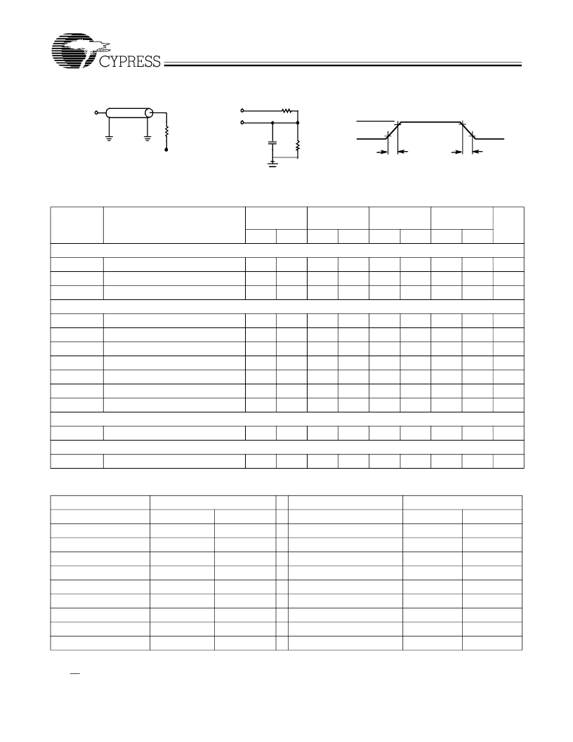
AC Test Loads and Waveforms
DQ
317
351
5 pF
(a)
(b)
DQ
50
Z
0
=50
V
t
= 1.5V
3.3V
ALL INPUT PULSES
3.0V
0V
90%
10%
90%
10%
≤
1.5 ns
≤
1.5 ns
(c)
Switching Characteristics
Over the Operating Range
[23]
-4
250 MHz
Min.
-4.4
225 MHz
Min.
-5
200 MHz
Min.
-6
166 MHz
Min.
Parameter
Description
Max.
Max.
Max.
Max.
Unit
Clock
t
KC
t
KH
t
KL
Output Times
t
KQ
t
KQX
t
KQLZ
t
KQHZ
t
OEQ
t
OELZ
t
OEHZ
Set-up Times
t
S
Hold Times
t
H
Clock Cycle Time
4.0
4.4
5.0
6.0
ns
Clock HIGH Time
1.6
1.7
2.0
2.4
ns
Clock LOW Time
1.6
1.7
2.0
2.4
ns
Clock to Output Valid
2.5
2.5
2.5
3.5
ns
Clock to Output Invalid
Clock to Output in Low-Z
[14, 19, 24]
Clock to Output in High-Z
[14, 19, 24]
OE to Output Valid
[25]
OE to Output in Low-Z
[14, 19, 24]
OE to Output in High-Z
[14, 19, 24]
1.25
1.25
1.25
1.25
ns
0
0
0
0
ns
1.25
3.0
1.25
3.0
1.25
3.0
1.25
4.0
ns
2.5
2.5
2.5
3.5
ns
0
0
0
0
ns
2.5
2.5
2.5
3.5
ns
Address, Controls, and Data In
[26]
1.0
1.0
1.0
1.0
ns
Address, Controls, and Data In
[26]
1.0
1.0
1.0
1.0
ns
Typical Output Buffer Characteristics
Output High Voltage
V
OH
(V)
–
0.5
Pull-Up Current
I
OH
(mA) Min.
–
38
Output Low Voltage
V
OL
(V)
–
0.5
Pull-Down Current
I
OL
(mA) Min.
0
I
OH
(mA) Max.
–
105
I
OL
(mA) Max.
0
0
–
38
–
105
0
0
0
0.8
–
38
–
105
0.4
10
20
1.25
–
26
–
83
0.8
20
40
1.5
–
20
–
70
1.25
31
63
2.3
0
–
30
1.6
40
80
2.7
0
–
10
2.8
40
80
2.9
0
0
3.2
40
80
3.4
0
0
3.4
40
80
Notes:
23. Test conditions as specified with the output loading as shown in part (a) of AC Test Loads unless otherwise noted.
24. At any given temperature and voltage condition, t
is less than t
KQLZ
and t
OEHZ
is less than t
OELZ
.
25. OE is a
“
don
’
t care
”
when a byte write enable is sampled LOW.
26. This is a synchronous device. All synchronous inputs must meet specified set-up and hold time, except for
“
don
’
t care
”
as defined in the truth table.
相關(guān)PDF資料 |
PDF描述 |
|---|---|
| GVT71128DA36B-6 | x36 Fast Synchronous SRAM |
| GVT71128DA36T-4 | x36 Fast Synchronous SRAM |
| GVT71128DA36T-4.4 | x36 Fast Synchronous SRAM |
| GVT71128DA36T-5 | x36 Fast Synchronous SRAM |
| GVT71128DA36T-6 | x36 Fast Synchronous SRAM |
相關(guān)代理商/技術(shù)參數(shù) |
參數(shù)描述 |
|---|---|
| GVT71128DA36B-6 | 制造商:未知廠家 制造商全稱:未知廠家 功能描述:x36 Fast Synchronous SRAM |
| GVT71128DA36T-4 | 制造商:Rochester Electronics LLC 功能描述:- Bulk |
| GVT71128DA36T-4.4 | 制造商:未知廠家 制造商全稱:未知廠家 功能描述:x36 Fast Synchronous SRAM |
| GVT71128DA36T-5 | 制造商:未知廠家 制造商全稱:未知廠家 功能描述:x36 Fast Synchronous SRAM |
| GVT71128DA36T-6 | 制造商:未知廠家 制造商全稱:未知廠家 功能描述:x36 Fast Synchronous SRAM |
發(fā)布緊急采購,3分鐘左右您將得到回復(fù)。