- 您現(xiàn)在的位置:買賣IC網(wǎng) > PDF目錄370396 > GT4123ACDA Analog Multiplier PDF資料下載
參數(shù)資料
| 型號: | GT4123ACDA |
| 英文描述: | Analog Multiplier |
| 中文描述: | 模擬乘法器 |
| 文件頁數(shù): | 2/15頁 |
| 文件大?。?/td> | 387K |
| 代理商: | GT4123ACDA |

520 - 44 - 00
The topology is designed so that once the control voltage
reaches either end of its range, the channel which is ON
remains fully ON and the OFF channel remains fully OFF.
This is critical for good off-isolation performance.
Most of the internal circuitry of the GT4124 is identical to that
of the GT4122. The unique feature of the GT4124 is the
addition of an accurate and stable strobed clamp.
Figure 2, shows the topology of the GT4124 and includes the
strobed clamp block. This circuit samples the OUTPUT signal
when CL
is connected to the OUTPUT, and compares it to
a CLAMP REFERENCE voltage which normally is set to 0V.
During the strobe period, which is usually the back porch
period of the video signal, DC feedback is applied to the
summing circuit
Σ
4 located between the output of the mixers
and the input of the output amplifier such that the DC offset is
held to within one or two millivolts of the clamp REFERENCE.
A holding capacitor C
HOLD
is used to assure effective clamp
operation and filter residual noise.
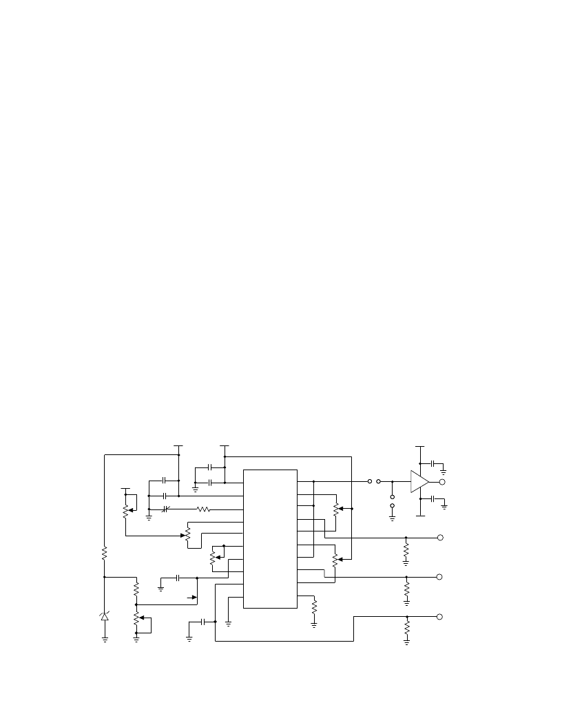
Fig. 3 GT4122 Test Circuit
0.1 or
LINK
GT4122
CONTROL
OFFSET
RV2
100
C3
0.1
C
OUT
-5V
C6
0.1
R
10k or
OPEN
+5V
B VIDEO INPUT
CONTROL INPUT
Z1
6.2V
R3
1k
RV1
200
R2
1k
C2
0.1
R1
560
(0.5V)
R4
5.6k
50%
GAIN
B BLACK
LEVEL
ADJUST
A BLACK
LEVEL
ADJUST
75
if required
RV4
500
RV5
500
1
2
4
3
17
18
19
20
+10V
-10V
-
V
S
GND
COMP
C
OS1
OUT
B
OS2
6
5
7
15
16
14
+
IN B
S1
-
IN B
A
OS2
-
IN A
9
8
10
12
13
S 2
V
REF
+
IN A
A
OS1
11
C5
47
-
10V
C5
47
C1
0.1
5 - 25pF
C
COMP
RV6
1k
V
ADJUST
RV3
SPAN
ADJUST
C5
0.1
+
V
S
C
OS2
V
C
R
EXT
B
OS1
C7
0.1
A VIDEO INPUT
75
if required
75
if required
IC2
CLC110
1
4
5
8
+
+
VIDEO OUT
1k
NOTE:
1.C5 is used when the CONTROL VOLTAGE (V
) is derived from a power supply.
2. All resistors in ohms, all capacitors in
μ
F unless otherwise stated.
Video applications for the GT4122, and GT4124 range from
simple two input mixers using a single device to a multi-
functional production switcher performing many video effects
including fading, wiping and keying, by cascading several
devices.
Figure 3 shows the GT4122 used as a two input video mixer.
An evaluation PC board has been made and the artwork is
GT4122 CIRCUIT APPLICATIONS
included. Using this circuit, many of the critical circuit
parameters can be measured including Crossfade Balance,
Linearity, Bandwidth and Differential Gain and Phase.
An output amplifier is shown but is only necessary when
driving low impedance loads such as co-axial cables. The
load on the GT4122 output itself should be kept above 5k
.
will be configured for unity gain by connecting both inverting
inputs (-IN A , -IN B) to the common output (OUT). In this
case, the general transfer function is:
V
O
= V
A
[V
NOM
+ A
K
(V
C
- V
REF
)] + V
B
[V
NOM
- A
K
(V
C
- V
REF
)]
(Unity gain configuration)
Where V
A
and V
B
are the input analog signals applied to +IN A
and +IN B respectively, and V
C
is the CONTROL voltage.
Note that V
NOM
ranges between 0.45V < V
NOM
< 0.55.
For normal video mixer operation, the control range (SPAN) is
usually 0 to 1V and will occur when A
=1, V
= 0.5V and
V
=0.5 volts. A change in V
from 0 to 1V will then produce
an effect such that the output signal contains 100% of Channel
B when V
is 0V and 100% of Channel A when V
is 1 volt. For
the above conditions, the general unity gain transfer function
reduces to:
V
O
= V
A
V
C
+ V
B
(1-V
C
)
Since the operation of the mixer is limited to one quadrant, no
signal inversions occur if the control voltage exceeds the
range zero to one volt in either direction.
相關(guān)PDF資料 |
PDF描述 |
|---|---|
| GT4123ACKA | Analog Multiplier |
| GT4123-CDA | Analog Multiplier |
| GT4123-CKA | Analog Multiplier |
| GT4124 | Trimmable Two Input Analog Mixers |
| GT4124-CDF | Analog Multiplier |
相關(guān)代理商/技術(shù)參數(shù) |
參數(shù)描述 |
|---|---|
| GT4123ACKA | 制造商:Rochester Electronics LLC 功能描述: 制造商:Gennum Corporation 功能描述: |
| GT4123ACKAE3 | 制造商:Rochester Electronics LLC 功能描述: 制造商:Gennum Corporation 功能描述: |
| GT4123B | 制造商:未知廠家 制造商全稱:未知廠家 功能描述:Two Channel Video Multiplier |
| GT4123BCDA | 制造商:Rochester Electronics LLC 功能描述: 制造商:Gennum Corporation 功能描述: |
| GT4123BCKA | 制造商:Rochester Electronics LLC 功能描述: 制造商:Gennum Corporation 功能描述: |
發(fā)布緊急采購,3分鐘左右您將得到回復(fù)。